Liquid feeding member for liquid ejection head, liquid ejection device, and image forming apparatus

a liquid ejection device and liquid feeding technology, applied in the direction of printing, inking apparatus, etc., can solve the problems of ejection failure, bubble entry into the liquid chamber, and increase the risk of ejection failure, so as to prevent adverse effects

Inactive Publication Date: 2009-11-19
RICOH KK
View PDF8 Cites 34 Cited by
  • Summary
  • Abstract
  • Description
  • Claims
  • Application Information

AI Technical Summary

Benefits of technology

[0015]In view of the foregoing, the present invention is directed to provide a liquid feeding member for a liquid ejection head which liquid feeding member discharges bubbles in a liquid feed path, including bubbles introduced from the head, using a circulating current without throwing away the liquid to the outside and prevents adverse effects such as meniscuses being broken due to pressure of the circulation. The present invention is also directed to provide a liquid ejection device, and an image forming apparatus including this liquid feeding member.

Problems solved by technology

However, if the length of the head is increased to have more nozzles, the risk of ejection failure increases.
One cause of the ejection failure is entry of bubbles into the liquid chamber.
The bubbles in the liquid chamber may prevent ink from being fed, resulting in ejection of no ink, or may reduce pressure for ejecting droplets, resulting in poor ejection.
Bubbles, even if they are small, near the nozzle, for example, cause ejection of liquid droplets in wrong directions, thereby failing to form an intended image.
When discharging bubbles using these methods, although there are methods to recycle the discharged ink, a large volume of ink is generally used and wasted without being used for image formation.
However, if the bubbles in the ink feed path are discharged by circulating the ink, a meniscus in the nozzle of the head is broken due to pressure of ink circulation, so that the ink oozes off or the bubbles are introduced from the nozzle.
However, in the case of the ink jet recorder of Patent Document 2 in which the nozzle face is sealed while circulating liquid, it is difficult to completely seal the nozzle face if a head is long.
Further, images cannot be formed by ejecting liquid while circulating the liquid.
However, if bubbles generated in the individual liquid chambers and bubbles introduced from the nozzle are carried upstream due to buoyant forces, the bubbles remain in the portion near the individual liquid chambers because of the presence of the partition wall and cannot be discharged by the circulating current.

Method used


Image

  • Liquid feeding member for liquid ejection head, liquid ejection device, and image forming apparatus
  • Liquid feeding member for liquid ejection head, liquid ejection device, and image forming apparatus
  • Liquid feeding member for liquid ejection head, liquid ejection device, and image forming apparatus

Examples


second embodiment

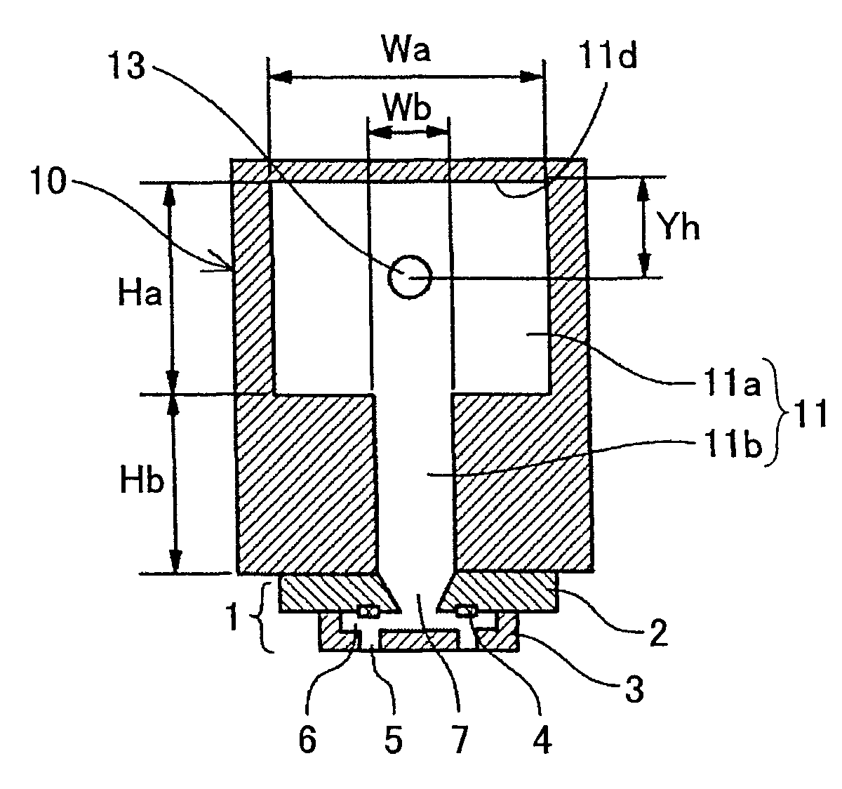
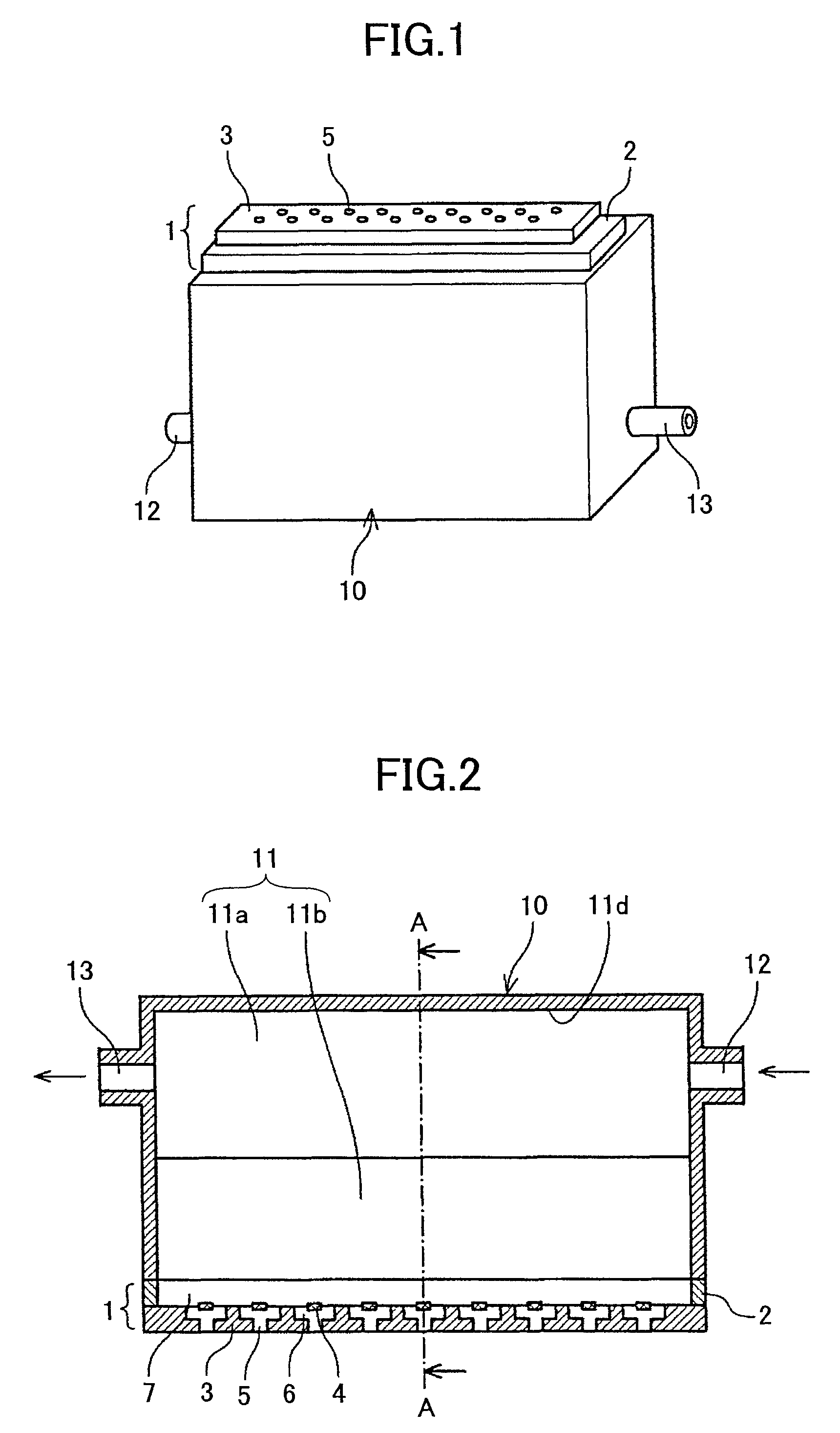
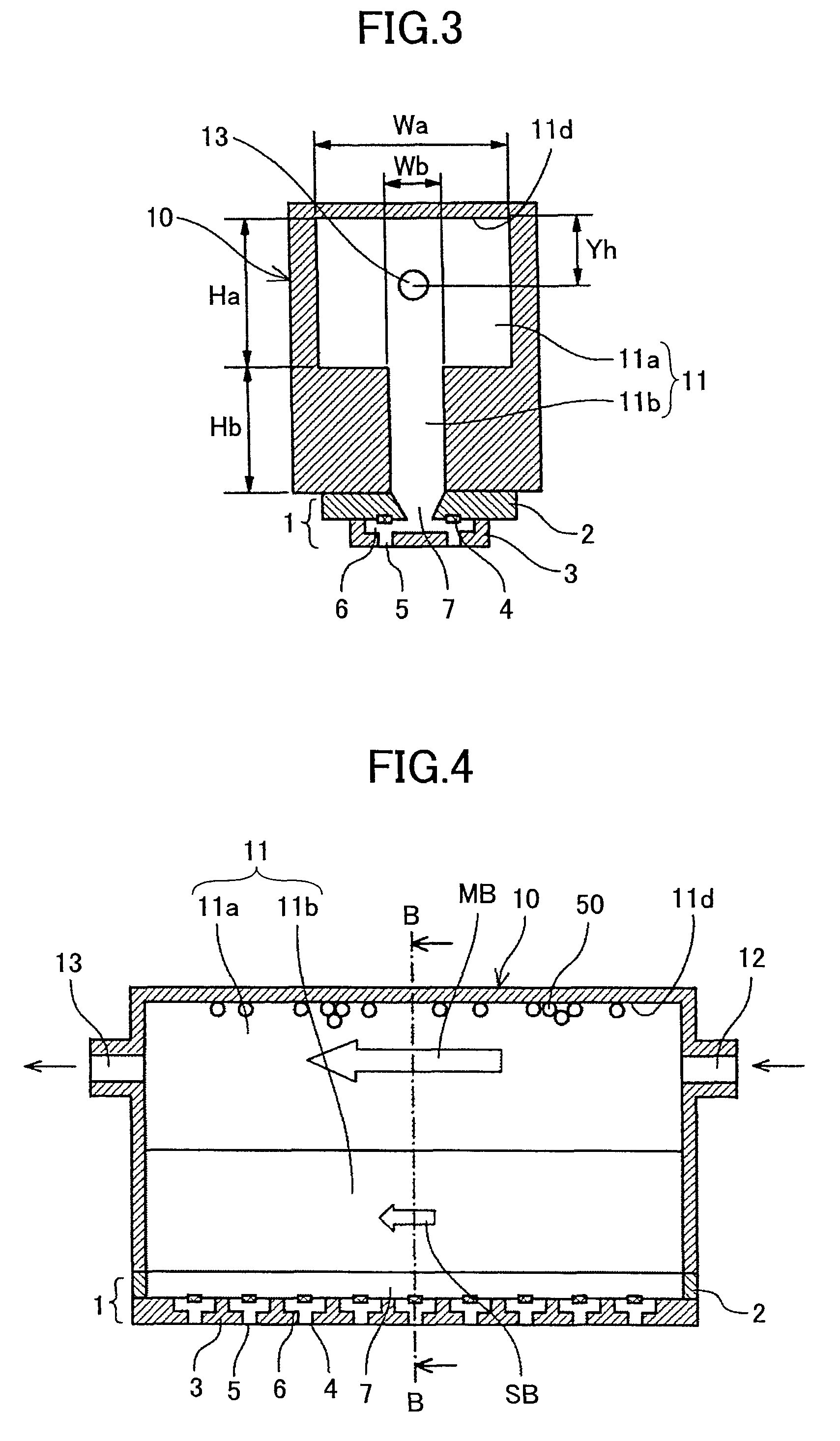
[0106]A liquid feeding member 10 of the present invention is described below with reference to FIGS. 11 through 13. FIG. 11 is a longitudinal cut-away view showing a head unit according to this embodiment. FIG. 12 is a cross-sectional view of the head unit taken along line E-E of FIG. 11. FIG. 13 is a cross-sectional view of the head unit taken along line F-F of FIG. 11.

[0107]In the liquid feeding member 10 of this head unit, a narrow communication passage 11b has different depths at the end portions where a feed port 12 and a discharge port 13 are disposed and the center portion.

[0108]More specifically, the region (feed-side region) within a distance (length) Ls from the feed port 12 and the region (ejection-side region) within a distance Ls from the discharge port 13 are defined as the end portions. The region excluding the feed-side region and the ejection-side region is defined as the center portion. A depth Hb of the narrow communication passage 11b is greater at the end portio...

third embodiment

[0112]A liquid feeding member 10 of the present invention is described below with reference to FIGS. 14 through 16. FIG. 14 is a longitudinal cut-away view showing a head unit according to this embodiment. FIG. 15 is a cross-sectional view of the head unit taken along line G-G of FIG. 14. FIG. 16 is a cross-sectional view of the head unit taken along line H-H of FIG. 14.

[0113]In the liquid feeding member 10 of this head unit, a communication opening 17 communicating with a common liquid chamber 7 of a liquid ejection head 1 is formed at the side of the common liquid chamber 7 in a liquid circulation path 11. Around the communication opening 17 are disposed plural ribs 16 upright toward the main passage 11a.

[0114]The provision of the ribs 16 increases the contact area between the circulating liquid and the wall at the side of the common liquid chamber 7 in the liquid circulation path 11. Accordingly, when the liquid inside the liquid feeding member 10 is circulated, the circulating ...

fourth embodiment

[0116]A liquid feeding member 10 of the present invention is described below with reference to FIGS. 17 through 19. FIG. 17 is a longitudinal cut-away view showing a head unit according to this embodiment. FIG. 18 is a cross-sectional view of the head unit taken along line I-I of FIG. 17. FIG. 19 is a cross-sectional view of the head unit taken along line J-J of FIG. 17.

[0117]In the liquid feeding member 10 of this head unit, plural ribs 16 are formed on the inner wall at the side of a common liquid chamber 7 of a liquid ejection head 1. Each rib 16 has different heights at the end portions where a feed port 12 and discharge port 13 are disposed and at the center portion.

[0118]More specifically, similar to the second embodiment, the region (feed-side region) within a distance Ls from the feed port 12 and the region (ejection-side region) within a distance Ls from the discharge port 13 are defined as the end portions. The region excluding the feed-side region and the ejection-side re...


PUM


Abstract

A liquid ejection device ejects liquid droplets from a liquid ejection head. The liquid ejection device includes a liquid feeding member that feeds liquid to the liquid ejection head. The liquid feeding member is connected to a liquid ejection head to feed liquid to a common liquid chamber of the liquid ejection head, which liquid ejection head includes the common liquid chamber that supplies the liquid to plural individual liquid chambers communicating with plural nozzles that eject liquid droplets. The liquid feeding member includes a liquid circulation path through which the liquid circulates in a direction parallel to a direction in which the nozzles of the liquid ejection head are aligned.

Description

TECHNICAL FIELD[0001]The present invention relates to a liquid feeding member for a liquid ejection head, a liquid ejection device, and an image forming apparatus.BACKGROUND ART[0002]Image forming apparatuses (e.g. printers, fax machines, copiers, and multifunction machines having functions of these machines) are known that perform image formation by ejecting liquid such as ink onto a medium with use of, e.g., a liquid ejection device while transporting the sheet. The liquid ejection device comprises a recording head including a liquid ejection head (liquid droplet ejection head) for ejecting droplets of the liquid (recording liquid). It is to be noted that the term “medium” as used herein is hereinafter also referred to as “sheet”, the material of which is not limited to paper. The terms “medium to be recorded on”, “recording medium”, “transfer material”, and “recording sheet”, may be used as synonymous. The terms “recording”, “printing”, and “imaging” may be used as synonymous wit...

Claims


Application Information

Patent Timeline
Patent Type & Authority Applications(United States)
IPC IPC(8): B41J2/175
CPCB41J2/14145B41J2202/20B41J2202/12B41J2/17513
Inventor KATOH, TOMOMI
Owner RICOH KK
Why Eureka
Try Eureka