Liquid crystal display device

a liquid crystal display and display device technology, applied in non-linear optics, instruments, optics, etc., can solve the problems of non-satisfactory in some respects, non-uniform application of anchoring force on liquid crystal molecules within pixel regions, and unintentional distribution of response speed, so as to improve display quality of a va mode liquid crystal display device and improve the display quality of a multi-domain structure defined by an alignment film

Active Publication Date: 2009-11-19
SHARP KK
View PDF29 Cites 79 Cited by
  • Summary
  • Abstract
  • Description
  • Claims
  • Application Information

AI Technical Summary

Benefits of technology

[0056]According to the present invention, the display quality of a VA mode liquid crystal display device can be improved in terms of its viewing angle dependence, in particular. Also, according to the present invention, the display quality of a liquid crystal display device having a multi-domain structure defined by an alignment film can be improved.

Problems solved by technology

The viewing angle characteristic of LCDs has been improved to a certain degree but not satisfactorily in some respects.
If a slit or a rib is adopted, however, the anchoring force will be applied onto liquid crystal molecules non-uniformly within a pixel region because the slit or rib has a linear structure unlike the situation where the pretilt directions are defined by an alignment film in a conventional TN mode LCD.
As a result, the response speed may have a distribution unintentionally.

Method used


Image

  • Liquid crystal display device
  • Liquid crystal display device
  • Liquid crystal display device

Examples


Embodiment Construction

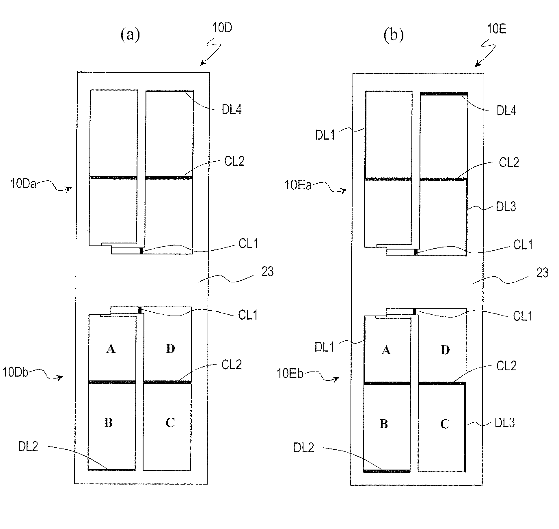
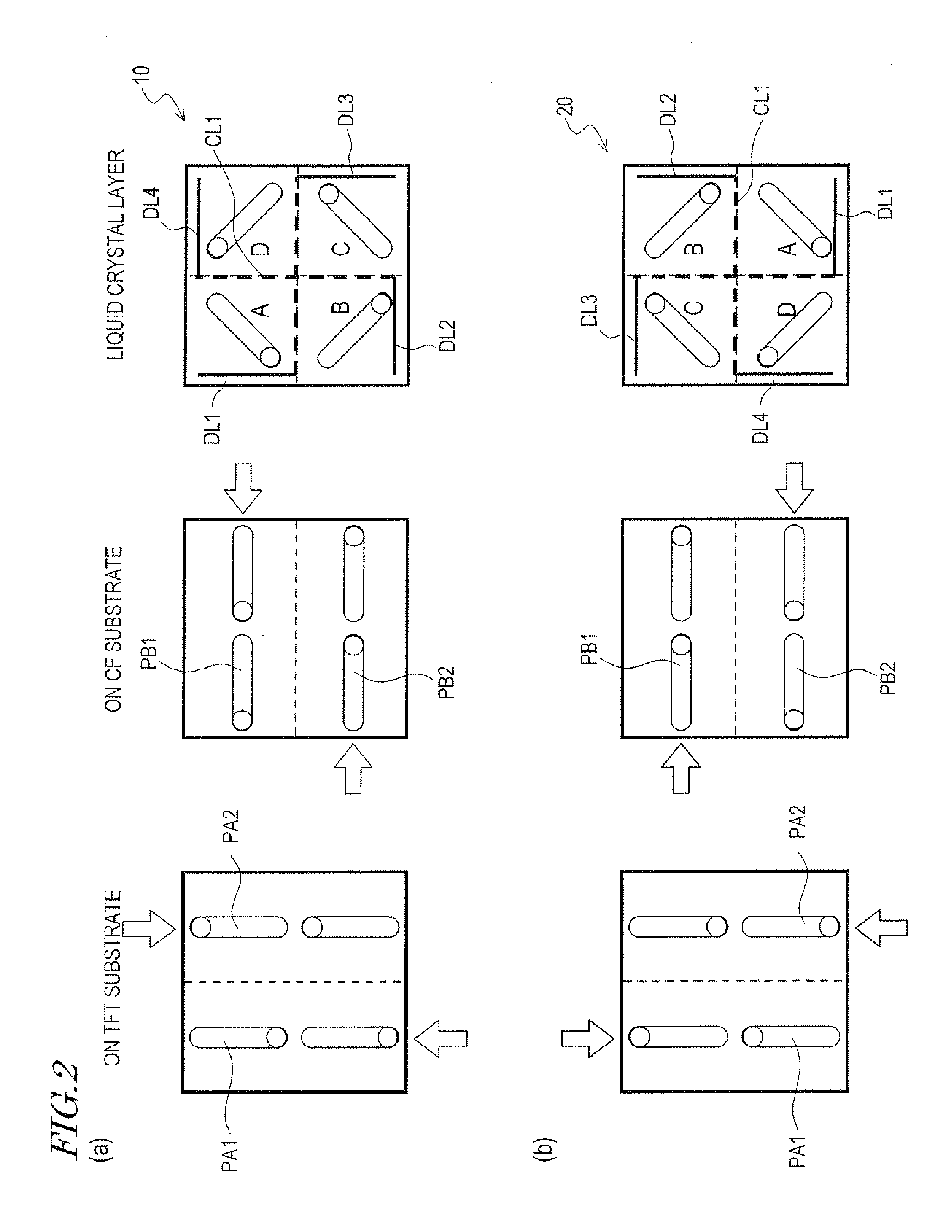
[0109]Hereinafter, embodiments of a liquid crystal display device according to the present invention will be described with reference to the accompanying drawings. However, the present invention is in no way limited to the following specific embodiments. According to the present invention, a liquid crystal display device, including a vertical alignment liquid crystal layer of which the pretilt direction is controlled by using at least one alignment film, has its display quality improved by providing an opaque film where misalignment occurs.

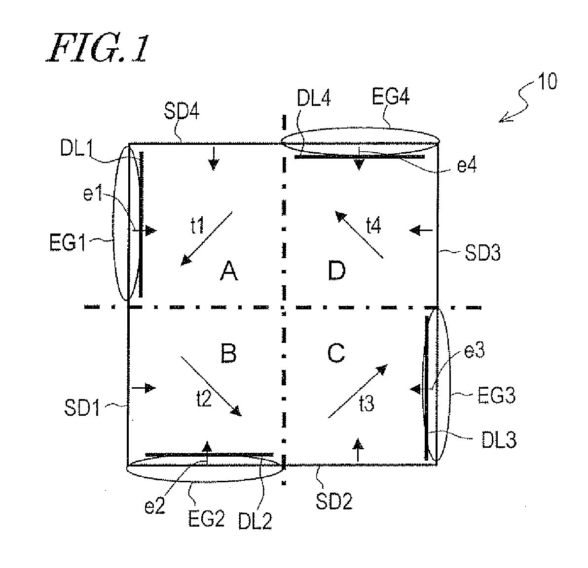
[0110]The display quality is affected to different degrees depending on where misalignment has occurred. That is why the type of misalignment to be hidden behind an opaque portion also changes with the display performance required. In the following description, three types of misalignment to occur in three different locations in a pixel region (namely, an electrode edge portion, a central portion and an intersection portion) will be described sepa...


PUM

PropertyMeasurementUnit
angleaaaaaaaaaa
azimuthal angleaaaaaaaaaa

Abstract

A liquid crystal display device includes: a vertical alignment liquid crystal layer; first and second substrates facing each other with the liquid crystal layer interposed; first and second electrodes arranged on the first and second substrates to face the liquid crystal layer; and at least one alignment film in contact with the liquid crystal layer. A pixel region includes a first liquid crystal domain in which liquid crystal molecules are tilted in a first direction around the center of a plane, and approximately at the middle of the thickness, of the liquid crystal layer responsive to a voltage applied. The first liquid crystal domain is close to at least a part of an edge of the first electrode. The part includes a first edge portion in which an azimuthal direction, perpendicular to the part and pointing toward the inside of the first electrode, defines an angle greater than 90 degrees to the first direction. The first or second substrate has an opaque member including a first opaque portion for selectively shielding at least a part of the first edge portion from incoming light.

Description

TECHNICAL FIELD[0001]The present invention relates to a liquid crystal display device and more particularly relates to a liquid crystal display device with a wide viewing angle characteristic.BACKGROUND ART[0002]Recently, the display performances of liquid crystal displays (LCDs) have been improved to the point that more and more manufacturers adopt LCD panels as TV monitors, for example. The viewing angle characteristic of LCDs has been improved to a certain degree but not satisfactorily in some respects. Among other things, there is still a high demand for improvement of the viewing angle characteristic of an LCD using a vertical alignment liquid crystal layer (which is sometimes called a “VA mode LCD”).[0003]A VA mode LCD, which is currently used for a TV set with a big screen, for example, adopts a multi-domain structure, in which multiple liquid crystal domains are formed in a single pixel region, to improve the viewing angle characteristic. An MVA mode is often adopted as a me...

Claims


Application Information

Patent Timeline
Patent Type & Authority Applications(United States)
IPC IPC(8): G02F1/1337
CPCG02F1/133512G02F1/133753G02F1/1337G02F2001/133757G02F1/1393G02F1/133757
Inventor SHORAKU, AKIHIROTSUBATA, TOSHIHIDEMIYACHI, KOICHIINOUE, IICHIROYAMAMOTO, AKIHIROHASHIMOTO, YOSHITOKUBO, MASUMIJINDA, AKIHITO
Owner SHARP KK
Why Eureka
Try Eureka