Implant and implantation system

a technology of implantation system and implantation device, which is applied in the field of implants and implantation systems, can solve the problems of high production cost of connecting device devices

Inactive Publication Date: 2009-11-19
AESCULAP AG
View PDF8 Cites 6 Cited by
  • Summary
  • Abstract
  • Description
  • Claims
  • Application Information

AI Technical Summary

Problems solved by technology

A disadvantage of the known bone screw lies in the type of connection which requires the adapter to be correctly placed on the head of the bone screw.
Furthermore, the production process for the connecting device is expensive.

Method used


Image

  • Implant and implantation system
  • Implant and implantation system
  • Implant and implantation system

Examples


Embodiment Construction

[0019]Although the invention is illustrated and described herein with reference to specific embodiments, the invention is not intended to be limited to the details shown. Rather, various modifications may be made in the details within the scope and range of equivalents of the claims and without departing from the invention.

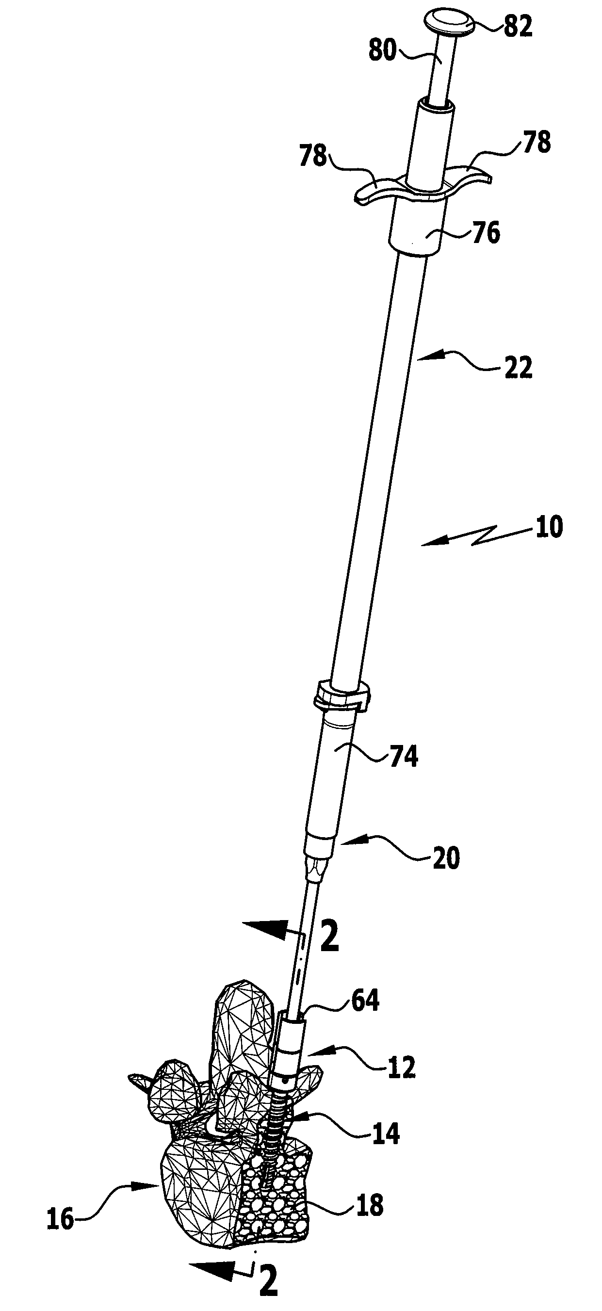
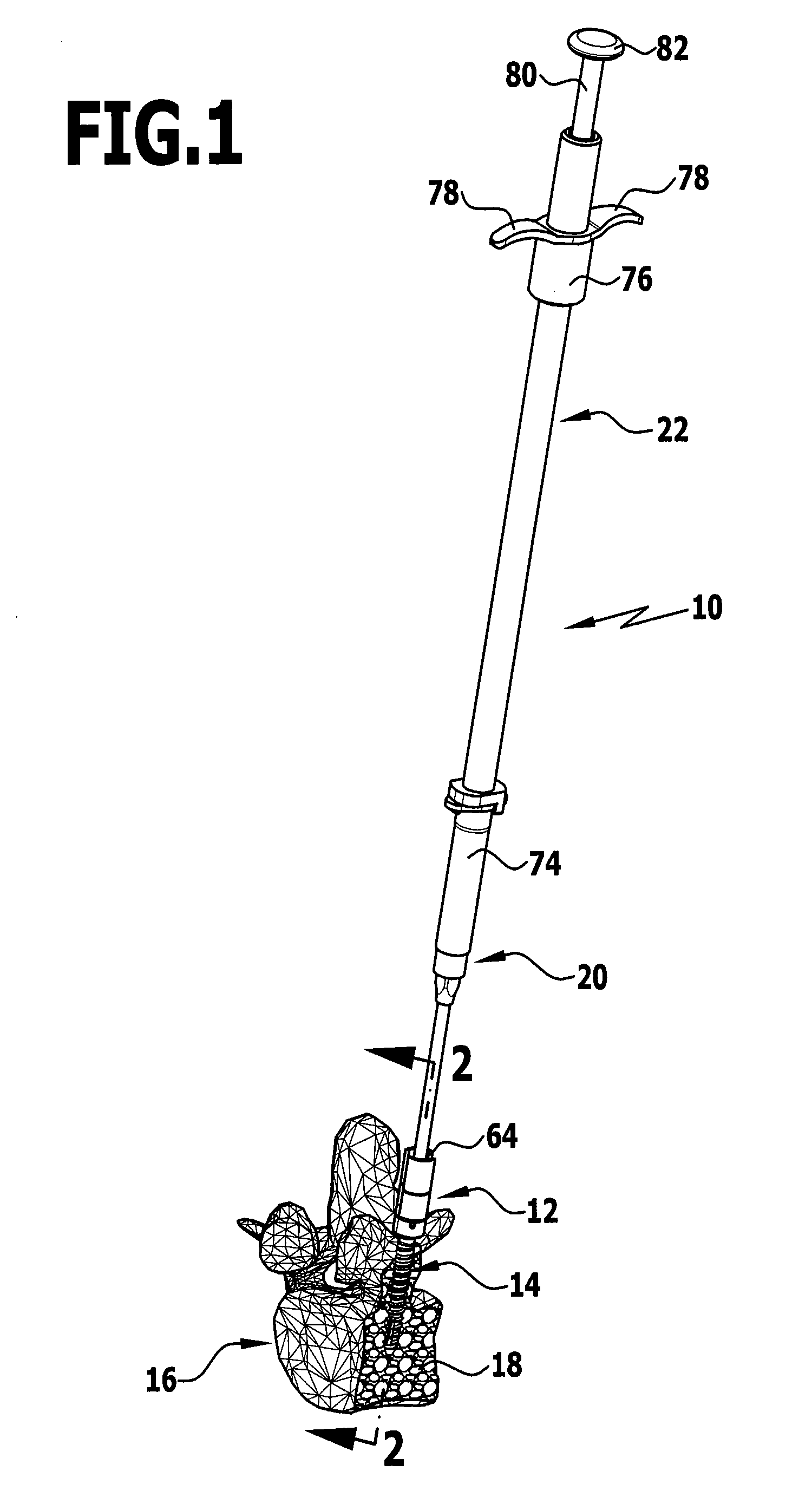
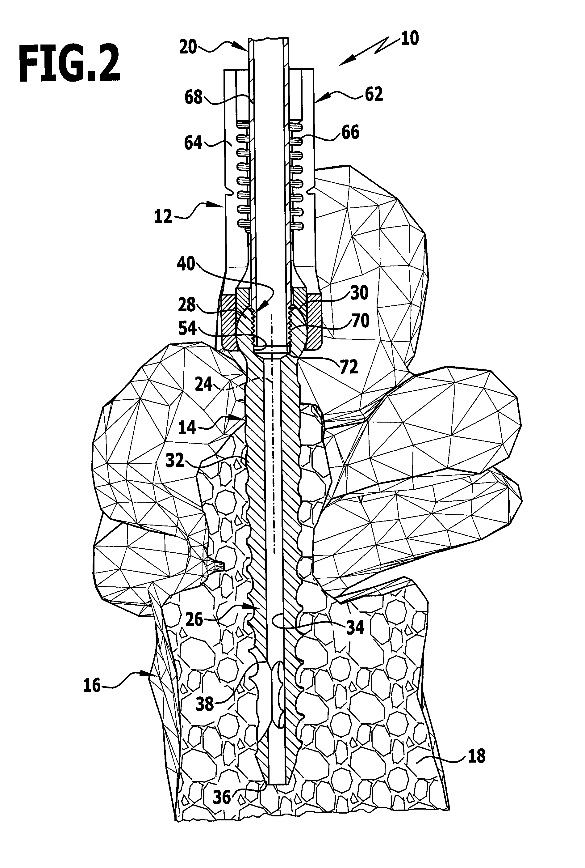
[0020]The present invention relates to an implant comprising a tool receiver for coupling to an implantation tool and also a connecting device for connecting the implant to an injection cannula for the purposes of injecting a bone bonding material, wherein the connecting device comprises an internally threaded section which is formed in or on the tool receiver.

[0021]Moreover, the present invention relates to an implantation system comprising at least one injection cannula for injecting a bone bonding material and at least one implant incorporating a tool receiver for coupling to an implantation tool and also a connecting device for connecting the implant to the at...


PUM


Abstract

An implant includes a tool receiver for coupling to an implantation tool and also a connecting device for connecting the implant to an injection cannula for the purposes of injecting a bone bonding material in such a manner that the handling and production thereof are simplified. The connecting device may include an internally threaded section which is formed in or on the tool receiver. An implantation system includes at least one injection cannula and at least one implant.

Description

CROSS-REFERENCE TO RELATED APPLICATIONS[0001]This application claims priority to German Patent Application number 10 2008 024 440.6 filed May 13, 2008, the contents of which is incorporated herein by reference in its entirety and for all purposes.FIELD OF THE INVENTION[0002]The present invention relates to an implant generally, and more specifically to an implant comprising a tool receiver for coupling to an implantation tool and also comprising a connecting device for connecting the implant to an injection cannula for the purposes of injecting a bone bonding material.[0003]Furthermore, the present invention relates to an implantation system generally, and more specifically to an implantation system comprising at least one injection cannula for injecting a bone bonding material and at least one implant incorporating a tool receiver for coupling to an implantation tool and also a connecting device for connecting the implant to the at least one injection cannula.BACKGROUND[0004]An imp...

Claims


Application Information

Patent Timeline
Patent Type & Authority Applications(United States)
IPC IPC(8): A61B17/58
CPCA61B17/7037A61B17/864A61B17/8615A61B17/7098
Inventor BEGER, JENSSCHUMACHER, JORGLINKE, RALPH
Owner AESCULAP AG
Why Eureka
Try Eureka