
Dental implant system

A technology of dental implants and implants, which is applied in dentistry, dental implants, dental restorations, etc., can solve the problems of large cutting resistance, stress concentration, deformation, etc., and achieve the effect of improving life expectancy, reliability, and performance

Pending Publication Date: 2019-01-01
NORTHEASTERN UNIV +1
View PDF8 Cites 1 Cited by
  • Summary
  • Abstract
  • Description
  • Claims
  • Application Information

AI Technical Summary

Problems solved by technology

From a mechanical point of view, when the vertical self-tapping groove is screwed into the connecting hole, the force of cutting the connecting hole on the end face of the vertical groove is concentrated on one line, which has a large cutting resistance and is prone to bone damage.
In addition, the bone chips generated during the self-tapping process of the vertical self-tapping groove cannot be discharged or accommodated, resulting in stress concentration at the corner of the end face of the vertical groove, and microcracks are prone to occur at the groove of the implant
Angled self-tapping grooves are easier to cut than vertical self-tapping grooves, but can only be used for implants with slender cylindrical structures
[0010] Existing abutments and implants are connected by four corners, hexagons and octagons. This connection method is prone to micro-rotation, even if it is fastened with connecting screws, it cannot avoid slight rotation
Micro-rotation causes local stress concentration on the implant, and long-term stress accumulation can easily cause damage and deformation of the joint
[0011] In this technical field, some implants are cylindrical, which is not easy to implant in the implant system; some implants generally use a single thread outside, so that the stress concentration point of the implant is at the interface between the alveolar bone and soft tissue, and it is difficult to ensure the stability of the implant system sex

Method used


Image

  • Dental implant system
  • Dental implant system
  • Dental implant system

Examples


Embodiment 1

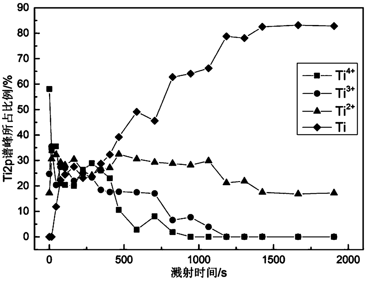
[0110] In this embodiment, metal titanium and titanium alloy are used as materials, which have good biocompatibility and mechanical processing performance. By performing sandblasting, acid etching and plasma oxidation treatment processes on the surface of titanium materials, the biological properties of implants can be effectively improved. Active, enhance the osseointegration performance of the implant.

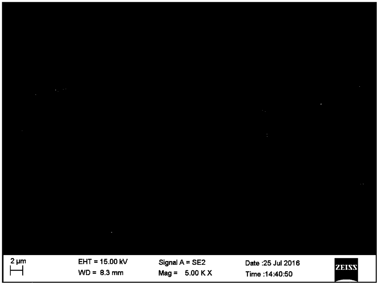
[0111] The surface of the implant is treated by sand blasting acid etching + plasma oxidation, such as figure 1 As shown, a titanium oxide layer structure with different valence states coexisting with gradient composition is prepared. Such as figure 1 As shown, the surface morphology of the prepared implant is an irregular porous oxide layer structure, and the micropores are closely arranged, which is conducive to the attachment of bone cells, suitable for the growth of alveolar bone, and can enhance the speed and quality of osseointegration. Among them, the O of the impla...

Embodiment 2

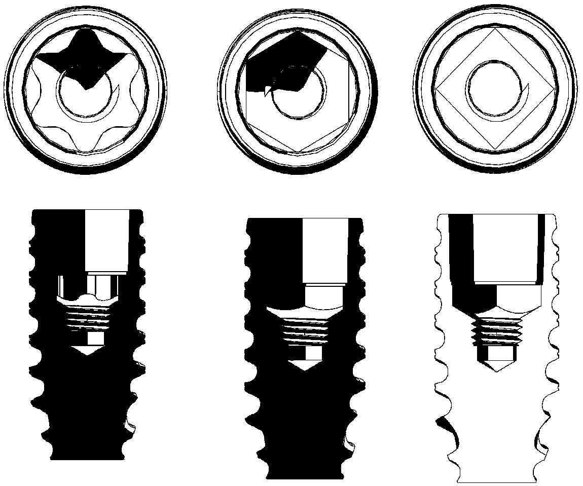
[0113] As shown in Figures 8 to 13, the dental implant system is composed of a straight abutment 1, a connecting screw 2 and an implant 3; the outer surface of the implant 3 is composed of two kinds of threads from top to bottom, and the whole body is made of the first The main thread 1-2 and the first thread 1-3 are combined to form a double thread; the outer head of the implant 3 is processed with a double leaf-shaped first self-tapping groove 1-7, and the top of the first implant head 1-8 It is a horizontal end face; and the implant is provided with a first tapered hole 1-1 with a taper of 3°, followed by a first Torx structure 1-4 at the lower part, and finally a first internal threaded hole 1-5. (See Figure 8 , Figure 9 , Figure 10 , Figure 11A , Figure 12 , Figure 13 )

[0114] Such as Figure 11A As shown, the internal structure of the implant body is set as a first tapered hole 1-1 with a taper of 3°, which is used in conjunction with the first Torx struct...

Embodiment 3

[0119]As shown in Figures 8 to 13, the dental implant system is composed of a straight abutment 1, a connecting screw 2 and an implant 3; the outer surface of the implant 3 is composed of two kinds of threads from top to bottom, and the whole body is made of the first The main thread 1-2 and the first thread 1-3 are combined to form a double thread; the outer head of the implant 3 is processed with a double leaf-shaped first self-tapping groove 1-7, and the top of the first implant head 1-8 and a first tapered hole 1-1 with a taper of 3° is provided inside the implant, followed by a Torx structure 1-4 at the lower part, and finally a first internal threaded hole 1-5.

[0120] The outside of the straight abutment 1 is composed of the first crown connecting section 1-12, the first gingival piercing section and the implant insertion section 1-13; The gingival segment and the implant insertion segment 1-13, the second Torx structure 1-14 cooperate with the first tapered hole 1-1 a...


PUM

PropertyMeasurementUnit
Maximum stressaaaaaaaaaa
Lengthaaaaaaaaaa
Diameter lengthaaaaaaaaaa

Abstract

The invention provides a dental implant system. The dental implant system comprises a base and an implant, wherein the base is connected with the implant in a matching way through an inner connectionstructure; the inner connection structure comprises a first torx ligand which is arranged in the implant, and a second torx ligand which is arranged at the bottom of the abutment; the first torx ligand can be matched with the second torx ligand, so that the abutment is connected with the implant. Through design of the structure of the implant and the abutment, a tight connection can be formed. A surface modification technology is adopted to treat the surface interface of the implant, so that the performance of bone bonding is improved, thereby prolonging the service life and improving the reliability of the implant system.

Description

technical field [0001] The invention relates to the technical field of oral medical devices, in particular to a dental implant system including surface modification technology and optimized design of implant, abutment and connecting screw connection systems, which can improve the biological stability and mechanical stability of the dental implant system sex. Background technique [0002] Tooth loss (including dentition defect and loss of dentition) is one of the most common oral diseases, which seriously affects the quality of life and physical and mental health of patients. There are more than 400 million edentulous patients in my country, which is close to 1 / 3 of the national population. The implant market is huge and has great potential for development. Therefore, in recent years, the market demand for tooth restoration is expanding day by day. Due to the incomparable advantages of dental implant restoration compared with traditional denture restoration (removable parti...

Claims


Application Information

Patent Timeline
IPC IPC(8): A61C8/00
CPCA61C8/0042A61C8/0074
Inventor 蔺增俞洋孙飞李新昌孙传盛许海
Owner NORTHEASTERN UNIV
Learn More