
Network Device

a network device and network technology, applied in data switching details, instruments, high-level techniques, etc., can solve the problems of user time and labor, network device not working, etc., to reduce time and labor of users

Inactive Publication Date: 2009-11-19
FUNAI ELECTRIC CO LTD
View PDF9 Cites 0 Cited by
  • Summary
  • Abstract
  • Description
  • Claims
  • Application Information

AI Technical Summary

Benefits of technology

[0008]An object of the present invention is to provide a network device which can recognize a server immediately after the network device is connected to the server via a LAN cable (network cable), and which can reduce time and labor of a user.
[0010]According to the network device of the present invention, the CPU can recognize the server immediately after the network cable is connected to the cable connecting unit, and hence immediately after the network device is connected to the server via the network cable. Further, since the CPU automatically recognizes the server, a user is not required to perform an operation (such as server list refreshing) to recognize the server (e.g. each time the network cable is connected to the cable connecting unit), thereby reducing time and labor of the user.

Problems solved by technology

Thus, the network device has a problem that the network device does not recognize the server immediately after the LAN cable is connected to the LAN jack.
However, the network device requires the user to operate and command the refreshing of the server list each time the LAN cable is connected to the LAN jack, so that there is a problem that the user is required to spend time and labor.
This network device is designed to automatically select an appropriate connection terminal in response to the detection of the connection or disconnection of the LAN cable, but is not designed to recognize a server connected thereto via the LAN cable immediately after the network device is connected to the server via the LAN cable.
Thus, this network device does not solve the above-described problem.
However, similarly as in the network system of the first patent publication, none of these network devices of the latter patent publications is designed to recognize a server connected thereto via a LAN cable immediately after the network device is connected to the server via the LAN cable.
Thus, these network devices do not solve the above-described problem either.

Method used


Image

  • Network Device
  • Network Device
  • Network Device

Examples


Embodiment Construction

[0019]Embodiments of the present invention, as best mode for carrying out the invention, will be described hereinafter with reference to the drawings. The present invention relates to a network device. It is to be understood that the embodiments described herein are not intended as limiting, or encompassing the entire scope of, the present invention. Note that like parts are designated by like reference numerals, characters or symbols throughout the drawings.

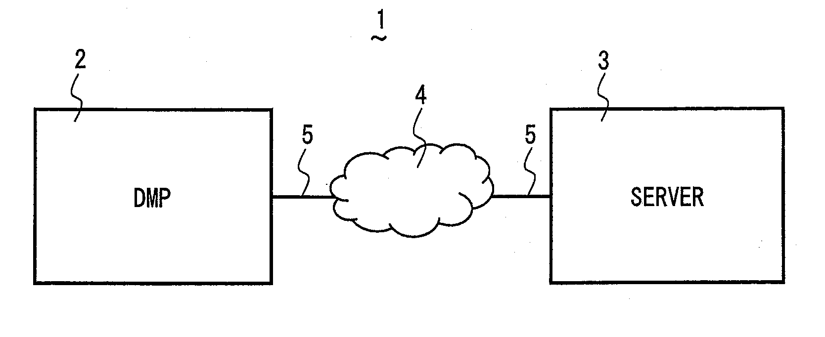
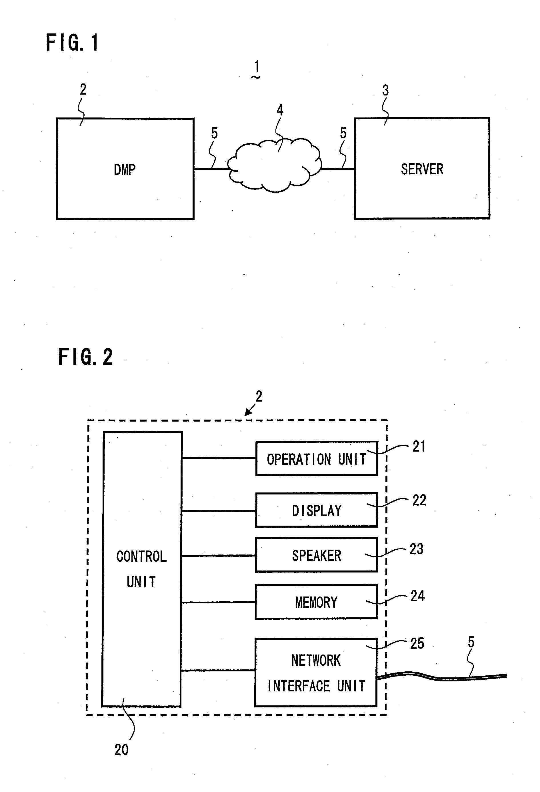
[0020]Referring to FIG. 1 and FIG. 2, a DMP (Digital Media Player corresponding to claimed “network device”) 2 according to an embodiment of the present invention will be described. FIG. 1 is a schematic block diagram of a network system 1 including a DMP 2 and a server 3. On the other hand, FIG. 2 is a schematic block diagram of the DMP 2, showing its inner structure. The DMP 2 and the server 3 can be connected to a network 4 via a LAN (Local Area Network) cable 5. The DMP 2 can reproduce content such as images (video) and audi...


PUM


Abstract

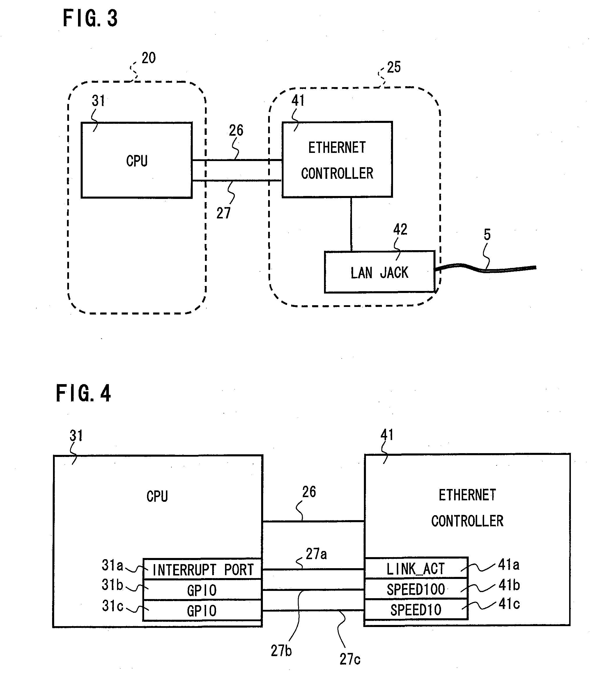
A network device to be connected to a server via a network comprises: a cable connecting unit connected to a network cable for connection to the network; a network controller for sending / receiving signals to / from the cable connecting unit and for detecting whether the network cable is connected to the cable connecting unit; a CPU for recognizing a server connected to the network; and a signal transmission line for transmission of a detection signal indicating that the network cable is connected to the cable connecting unit. When the CPU receives an interrupt signal from the network controller, the CPU performs a process to recognize the server connected to the network. This makes it possible for the CPU (hence the network device) to automatically recognize the server immediately after the network cable is connected to the cable connecting unit without requiring a user to spend time and labor for the server recognition.

Description

BACKGROUND OF THE INVENTION[0001]1. Field of the Invention[0002]The present invention relates a network device, and more particularly to a network device which can recognize a server immediately after the network device is connected to the server via a LAN cable.[0003]2. Description of the Related Art[0004]A network device such as DMP (Digital Media Player) is known which can be connected to a server via a network cable such as LAN (Local Area Network) cable (or simply network cable). When connected via a LAN cable to a server storing content, the network device obtains content data such as images from the server, and can reproduce the obtained content data. The network device is contained in a housing, and comprises a LAN jack provided exposed outside of the housing, and a control microcomputer for recognizing the server connected thereto via the LAN cable connected to the LAN jack, in which the control microcomputer recognizes the server at predetermined intervals. Thus, the netwo...

Claims


Application Information

Patent Timeline
IPC IPC(8): G06F15/173H04L12/28
CPCH04L12/12Y02B60/35Y02B60/34Y02D30/50
Inventor YOSHIOKA, SHINJI
Owner FUNAI ELECTRIC CO LTD
Learn More