Carriage traction vehicle

a technology of traction vehicle and rack, which is applied in the field of traction vehicle, can solve the problems of rack railway system derailment, system complexity, and inability to meet the needs of use, and achieve the effect of rails, reducing the number of racks, and improving the service li

Active Publication Date: 2009-11-26
HILLTRAC
View PDF25 Cites 13 Cited by
  • Summary
  • Abstract
  • Description
  • Claims
  • Application Information

AI Technical Summary

Benefits of technology

[0009]Embodiments of a vehicle for transporting a payload along a monorail are disclosed. According to one embodiment, the vehicle may include a cabin configured for carrying the payload. The embodiment of a vehicle may further include a counterwheel assembly configured for wheeled engagement around the monorail, the monorail configured with a triangular cross-section. The embodiment of a vehicle may further include a platform asse

Problems solved by technology

Such conventional rail transportation systems may not be suitable for use on steep grades where traction may become a problem.
However, these systems are inherently complex mechanical systems.
However, such rack railway systems suffer from derailments when the cogwheel slips out of the teeth in the rail rack.
Additionally, the rail rack itself is expensive to produce and maintain.
Furthermore, switches for rack railways are more complex because of the rail rack.
While these cable and chain-driven

Method used


Image

  • Carriage traction vehicle
  • Carriage traction vehicle
  • Carriage traction vehicle

Examples


Embodiment Construction

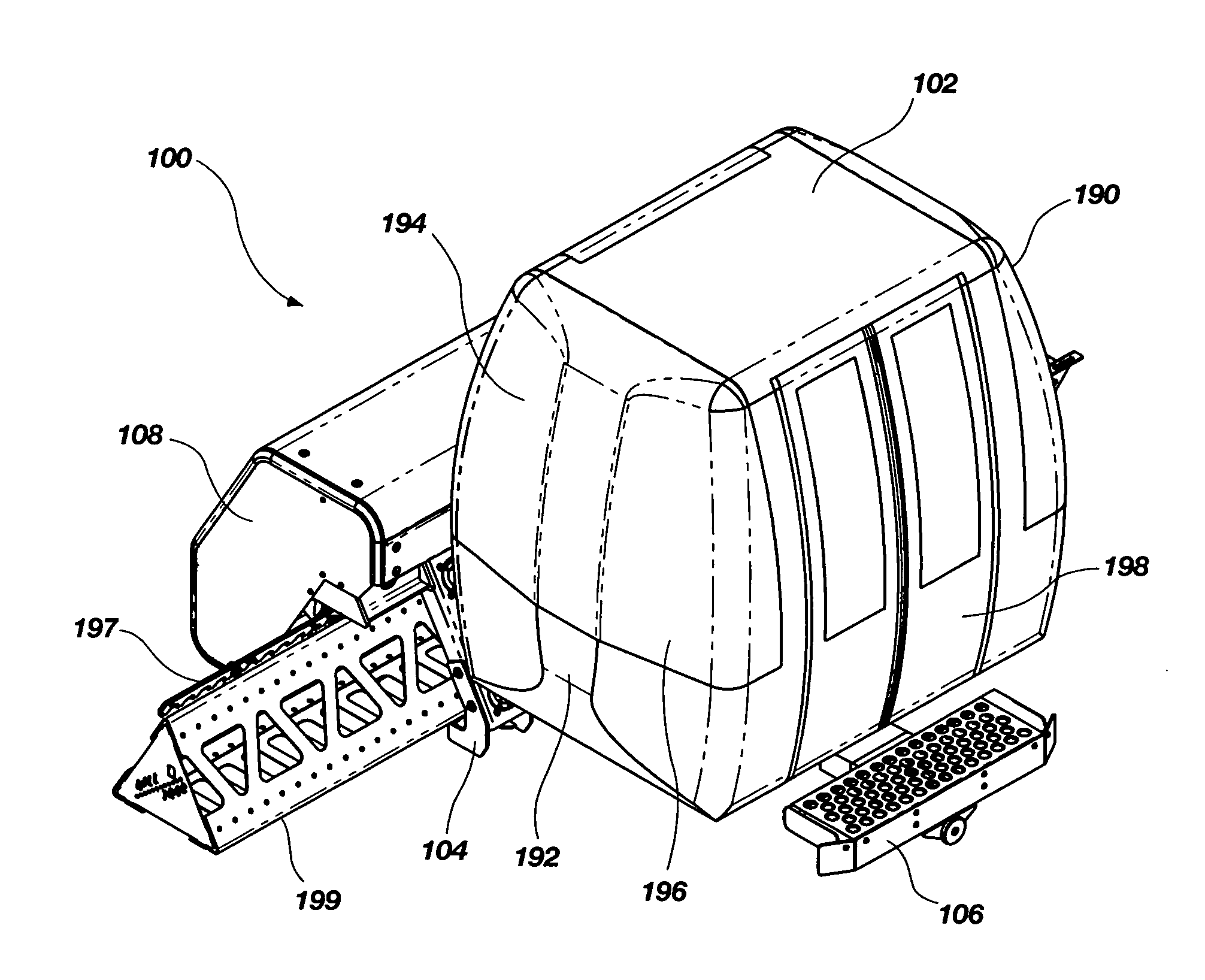
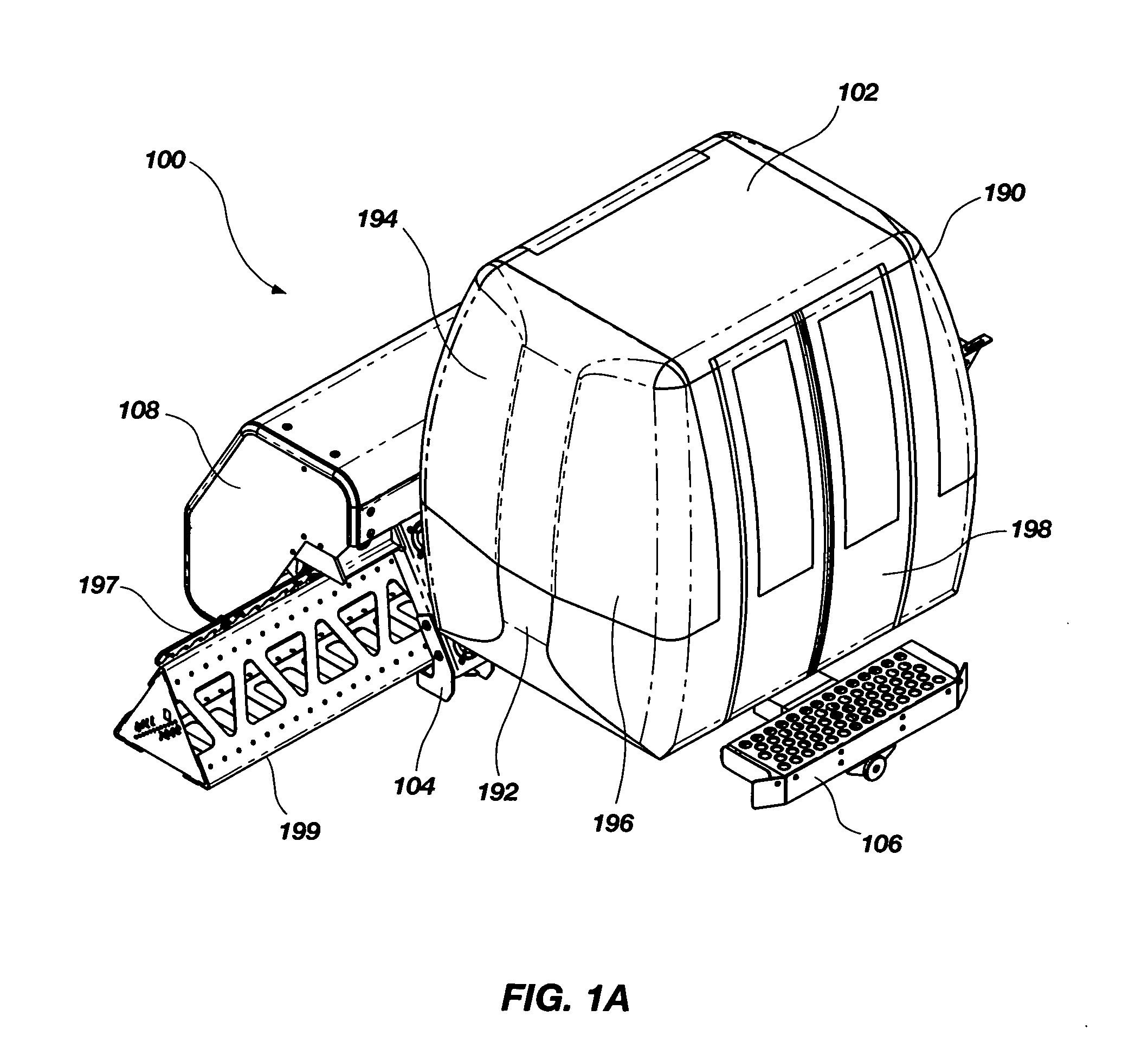
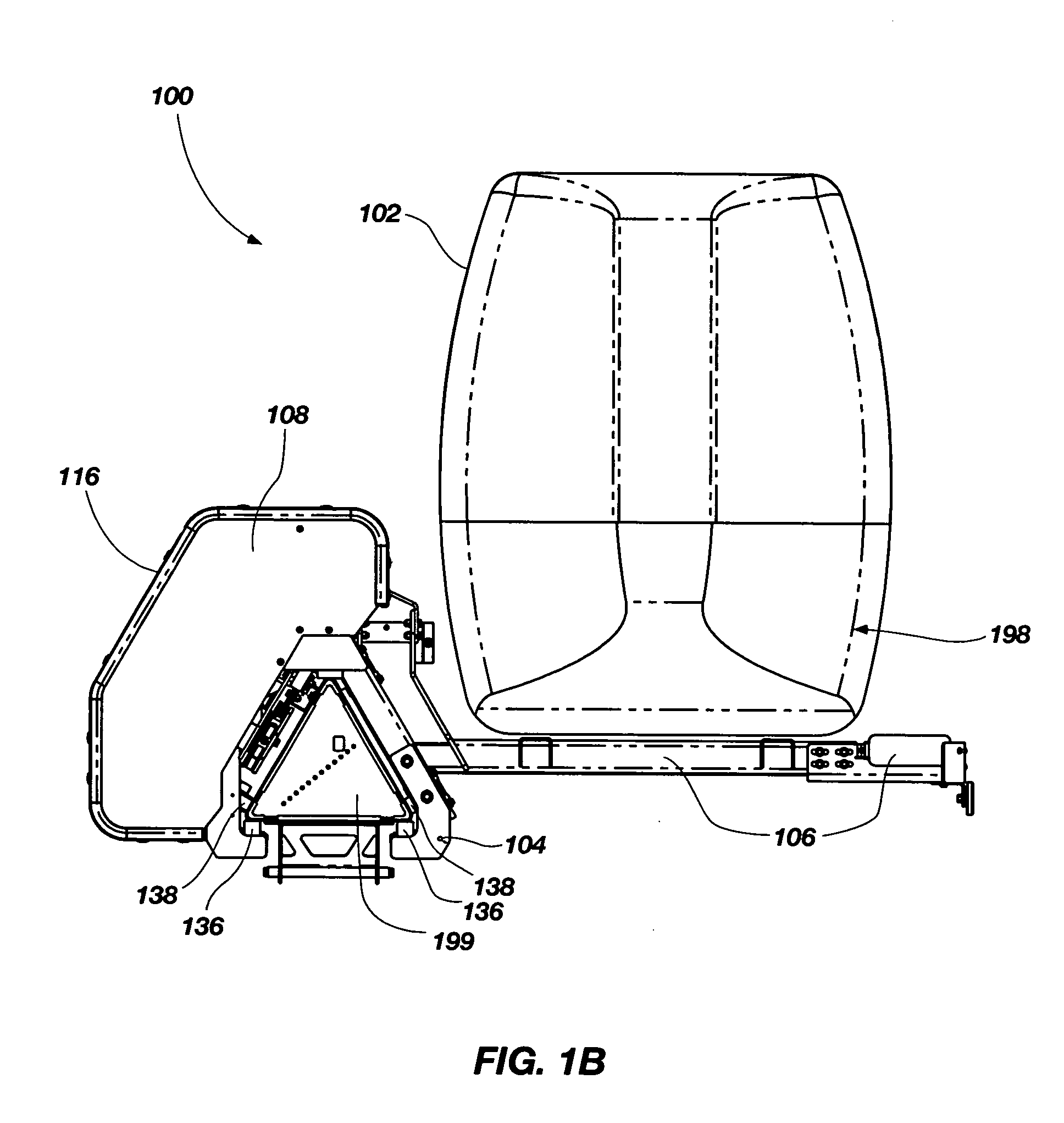
[0033]Reference will now be made to figures of embodiments of the present invention wherein like structures will be provided with like reference designations. It is understood that the drawings are diagrammatic and schematic representations of exemplary embodiments of the present invention and are neither limiting of the present invention nor are they necessarily drawn or shown to scale.

[0034]The Illustrated embodiments of the present invention include a triangle carriage traction vehicle configured for use on a triangular cross-sectioned monorail. An example of such a monorail is disclosed in U.S. patent application Ser. No. 12 / 075,619 filed on Mar. 12, 2008, titled “HOLLOW STRUCTURAL MEMBERS, A RAIL SYSTEM AND METHODS OF MANUFACTURING”, the contents of which are hereby incorporated by reference for all purposes. The embodiments of a vehicle disclosed herein are useful for transporting any kind of payload, e.g., passengers, bulk items and / or cargo, from one location to another in a...


PUM


Abstract

The invention is a carriage traction vehicle for use with a monorail. The vehicle is self-propelled along the monorail by one or more motors engaging a fixed rack attached to the monorail.

Description

CROSS-REFERENCE TO RELATED APPLICATIONS[0001]This nonprovisional patent application claims priority to U.S. provisional patent application Ser. No. 61 / 128,623, filed May 23, 2008, titled “TRIANGLE CARRIAGE TRACTION VEHICLE”, the contents of which are hereby incorporated by reference for all purposes. This nonprovisional patent application is also related to U.S. patent application Ser. No. 12 / 075,619 filed on Mar. 12, 2008, titled “HOLLOW STRUCTURAL MEMBERS, A RAIL SYSTEM AND METHODS OF MANUFACTURING”, pending and incorporated herein by reference for all purposes.BACKGROUND OF THE INVENTION[0002]1. Field of the Invention[0003]This invention relates generally to a vehicle for use in railed transportation systems. More particularly, the invention relates to a self-powered vehicle configured for operation on a monorail.[0004]2. Description of Related Art[0005]Railed transportation systems are well known in the art. Most conventional railways for transportation of people, goods and othe...

Claims


Application Information

Patent Timeline
IPC IPC(8): B61B13/04
CPCB61B13/02Y02T30/30E01B25/08B61B13/04Y02T30/00
Inventor HEPNER, ALANMETIVIER, DAVID
Owner HILLTRAC
Why Eureka
Try Eureka