
Apparatuses and Methods Relating to Precision Attachments Between First and Second Components

a technology of precision attachment and apparatus, applied in the direction of magnets, magnetic materials, magnetic bodies, etc., can solve the problems of many traditional mechanisms for securing and/or calibrating two parts that are relatively impermanent, and the relative position of the two parts can dri

Inactive Publication Date: 2009-11-26
CORRELATED MAGNETICS RES LLC
View PDF40 Cites 63 Cited by
  • Summary
  • Abstract
  • Description
  • Claims
  • Application Information

AI Technical Summary

Benefits of technology

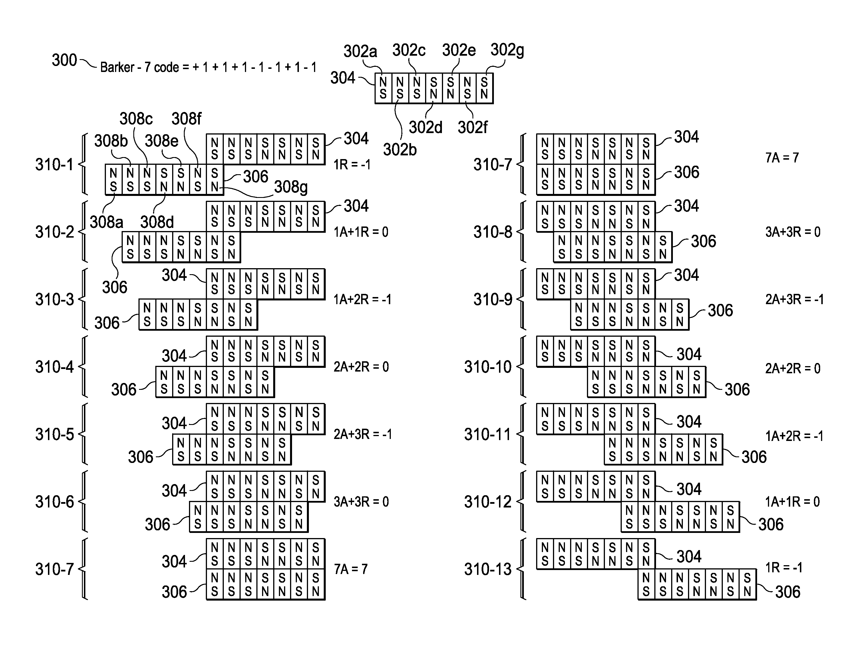
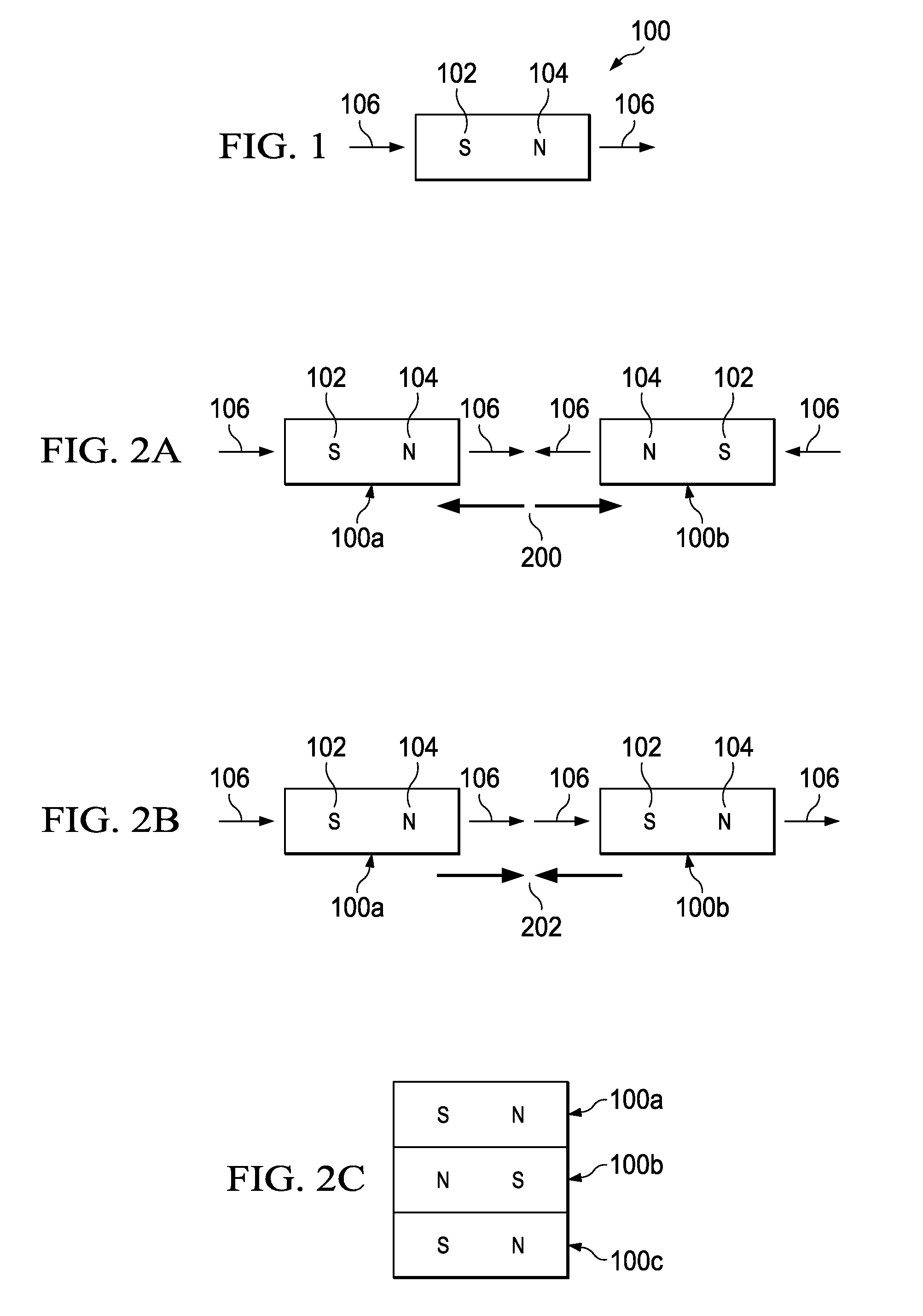
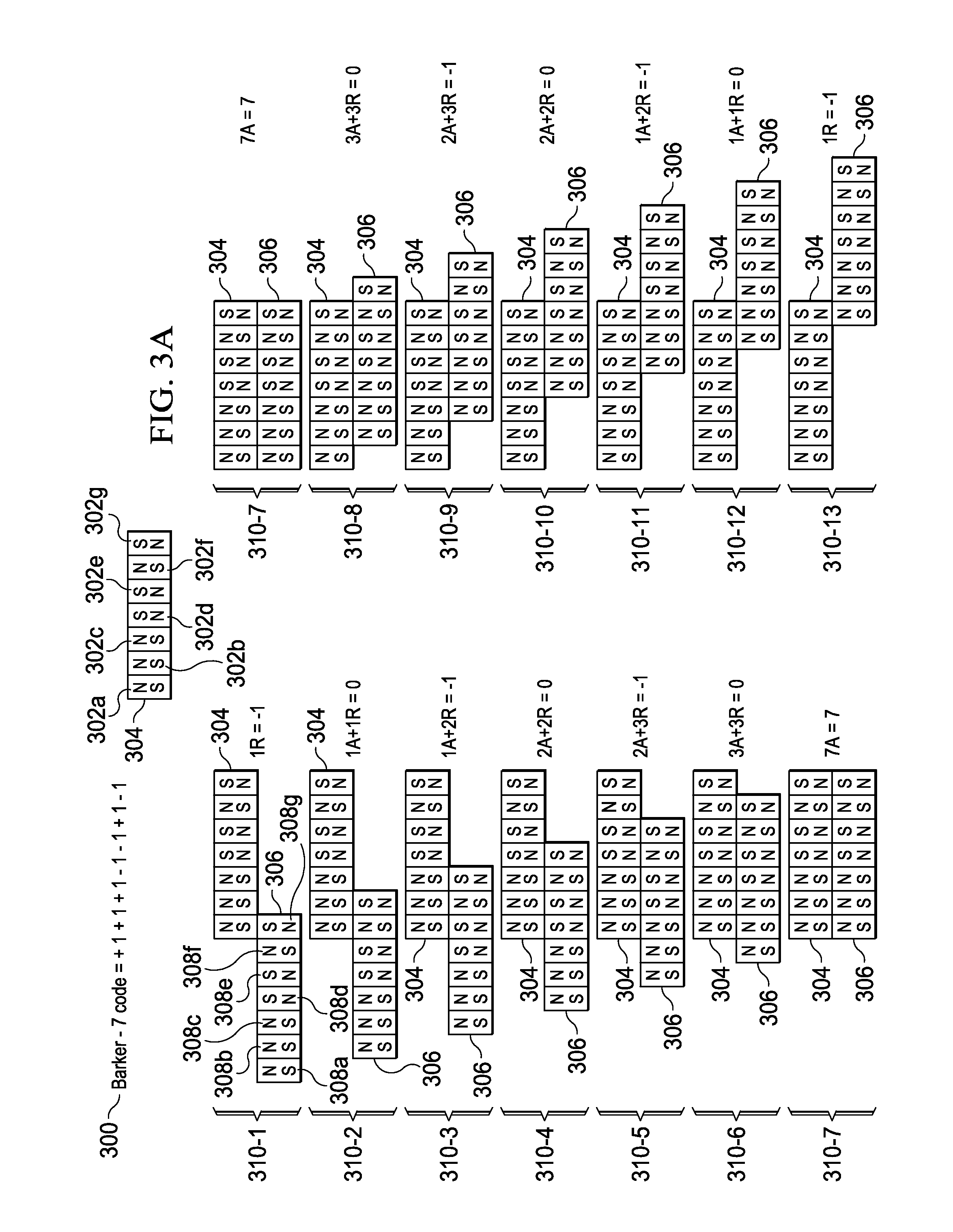
[0007]First and second components may be precisely attached to form an apparatus. In an example embodiment, an apparatus comprises a first component and a second component. The first component includes a first field emission structure. The second component includes a second field emission structure. The first and second components are adapted to be attached to each other with the first field emission structure in proximity to the second field emission structure such that the first and second field emission structures have a predetermined alignment with respect to each other. Each of the first and second field emission structures include multiple field emission sources having positions and polarities relating to a predefined spatial force function that corresponds to the predetermined alignment of the first and second field emission structures within a field domain. The first and second field emission structures are configured responsive to at least one precision criterion to enable a precision attachment.

Problems solved by technology

Unfortunately, this traditional manual approach to calibration is tedious and time consuming.
Moreover, many traditional mechanisms for securing and / or calibrating two parts are relatively impermanent.
In other words, the relative positions of the two parts can drift over time, such as through rough contact or mechanical vibrations, because the mechanisms used to secure the parts are not sufficiently stable and immobile.
Unfortunately, the manual calibrations and periodic recalibrations are expensive and time consuming.
Thus, it is apparent that conventional approaches to precisely aligning two parts of an apparatus entail significant manual adjustment.

Method used


Image

  • Apparatuses and Methods Relating to Precision Attachments Between First and Second Components
  • Apparatuses and Methods Relating to Precision Attachments Between First and Second Components
  • Apparatuses and Methods Relating to Precision Attachments Between First and Second Components

Examples


Embodiment Construction

[0023]Certain embodiments of the present invention relate to apparatuses that have a first component and a second component that may be attached to each other. In certain example implementations, each of the first component and the second component incorporate at least one correlated magnetic structure that enables the first component and the second component to be attached (e.g., removably connected) to each other with a predetermined precision or tolerance level. Apparatuses having precisely-attached components may be used for many purposes. Example purposes include, but are not limited to, optics, surveying, manufacturing, medical care, combinations thereof, and so forth. More specific examples include, but are not limited to, a gun scope or camera, a tripod or leveling apparatus; a metalworking or woodworking machine, a robotic machine, a semiconductor fabrication machine; an X-ray or other imaging machine; and so forth. Certain embodiments of the present invention are made poss...


PUM

PropertyMeasurementUnit
magnetic fieldaaaaaaaaaa
polaritiesaaaaaaaaaa
magnetic fieldaaaaaaaaaa

Abstract

First and second components may be precisely attached to form an apparatus. In an example embodiment, a first component includes a first field emission structure, and a second component includes a second field emission structure. The first and second components are adapted to be attached to each other with the first field emission structure in proximity to the second field emission structure such that the first and second field emission structures have a predetermined alignment with respect to each other. Each of the first and second field emission structures include multiple field emission sources having positions and polarities relating to a predefined spatial force function that corresponds to the predetermined alignment of the first and second field emission structures within a field domain. The first and second field emission structures are configured responsive to at least one precision criterion to enable a precision attachment.

Description

CROSS REFERENCES TO RELATED APPLICATIONS[0001]This application is a continuation-in-part application of U.S. patent application Ser. No. 12 / 476,952 filed on Jun. 2, 2009 and entitled “A Field Emission System and Method”, which is a continuation-in-part application of U.S. patent application Ser. No. 12 / 322,561 filed on Feb. 4, 2009 and entitled “A System and Method for Producing an Electric Pulse”, which is a continuation-in-part application of U.S. patent application Ser. No. 12 / 358,423 filed on Jan. 23, 2009 and entitled “A Field Emission System and Method”, which is a continuation-in-part application of U.S. patent application Ser. No. 12 / 123,718 filed on May 20, 2008 and entitled “A Field Emission System and Method”. The contents of these four documents are hereby incorporated herein by reference.TECHNICAL FIELD[0002]The present invention is related to apparatuses and methods that incorporate correlated magnets for precisely attaching first and second components. By way of examp...

Claims


Application Information

Patent Timeline
Patent Type & Authority Applications(United States)
IPC IPC(8): H01F7/02H01F7/00
CPCF41G11/001H01F7/0263H01F7/0215
Inventor FULLERTON, LARRY W.ROBERTS, MARK D.WILLIAMS, MITCHELL
Owner CORRELATED MAGNETICS RES LLC
Learn More