Self contained wall mountable surveillance and security system

a security system and self-contained technology, applied in the field of video surveillance and security, can solve the problems of inability of the security system to perform the desired task, cable runs in excess of hundreds of feet, and poor performan

Inactive Publication Date: 2009-11-26
LEFORT JASON GUY +1
View PDF19 Cites 50 Cited by
  • Summary
  • Abstract
  • Description
  • Claims
  • Application Information

AI Technical Summary

Benefits of technology

[0012]In the embodiment of this invention the use of specialized video surveillance pan, tilt and zoom cameras (PTZ cameras) with analytics capabilities and with the ability to, and working in conjunction and harmony with, the video encoder and the plurality of the entire surveillance system to autonomously and without human intervention to select, identify and track a specific intrusion and or target and with the ability to remain locked on said target regardless of movement or direction said target undertakes within the designated security zone to be protected, and to zoom in and capture real time images of said target and store data for later retrieval or to communicate said data in real time to an authorized user, but not limited to continually manned central monitoring stations, make this invention a clear and distinct improvement to the current embodiments of aforementioned surveillance systems. Secondly, the addition of the programmable LED digital message board offers a highly visible warning that the area is under video surveillance.

Problems solved by technology

As the need for security and monitoring increases additional cameras and equipment may be added, these additions are often comprised of mismatched components requiring additional wiring, complex time consuming installation, troubleshooting and maintenance, often resulting in poor performance and the inability of the security system to perform the desired task.
Security system cameras are generally mounted to the side of a building or wall, or often affixed to a pole or other structure that require extensive wiring and cabling, often resulting in cable runs in excess of hundreds of feet, this type of installation is often difficult, time consuming, inefficient, as well as expensive.
Often in these types of systems signal degradation occurs as a result of the extended length of said cable runs, requiring the addition of signal amplification and other equipment to provide a signal boost back to the video monitors at a central monitoring point.
In addition the difficulties of running wires and cable through and around buildings or over and under roadways and high traffic areas cause significant obstacles to this type of installation.
Additional upgrades, service, repair and maintenance to these types of surveillance systems are often difficult and inflexible due to the positioning of the required equipment.

Method used


Image

  • Self contained wall mountable surveillance and security system
  • Self contained wall mountable surveillance and security system
  • Self contained wall mountable surveillance and security system

Examples


Embodiment Construction

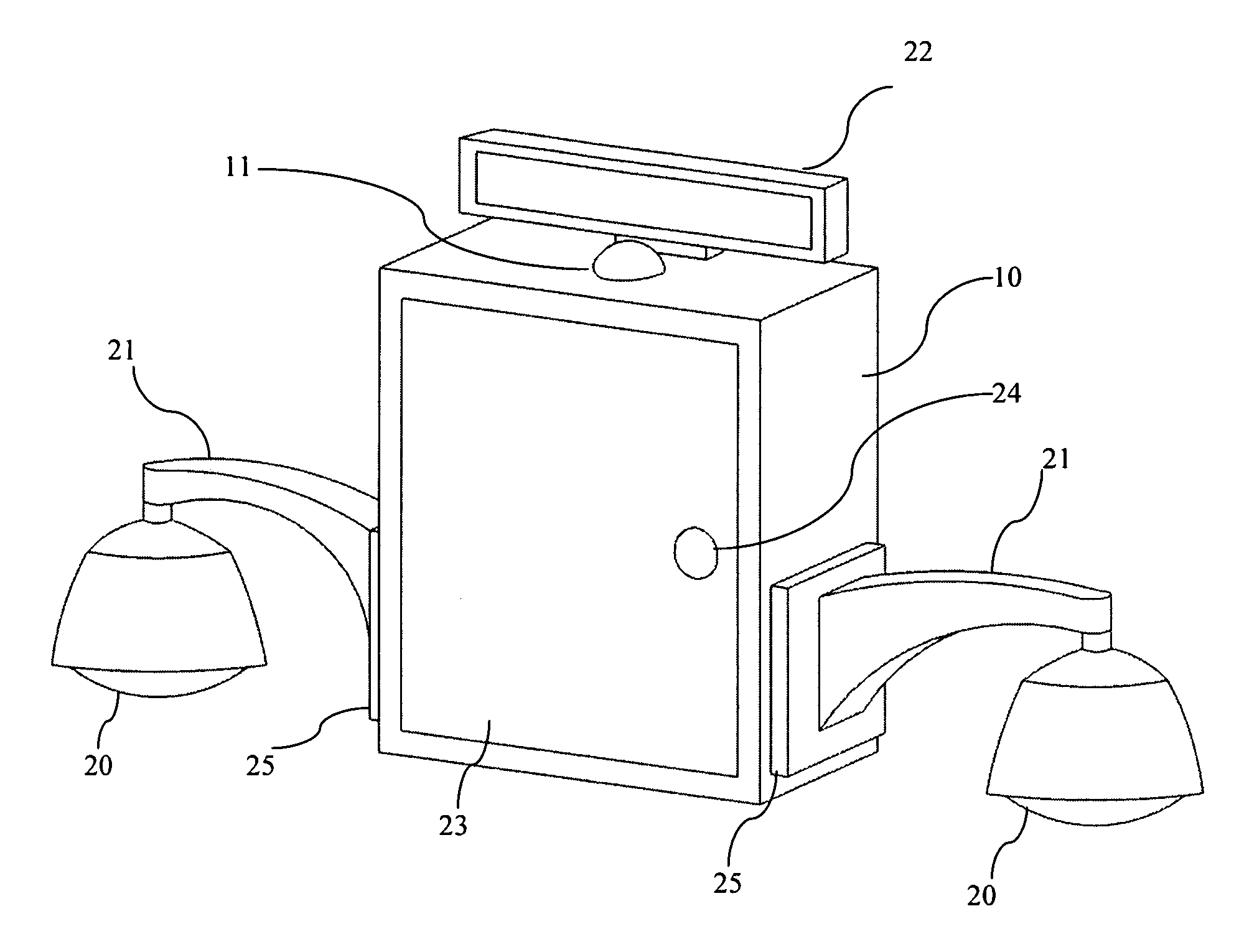
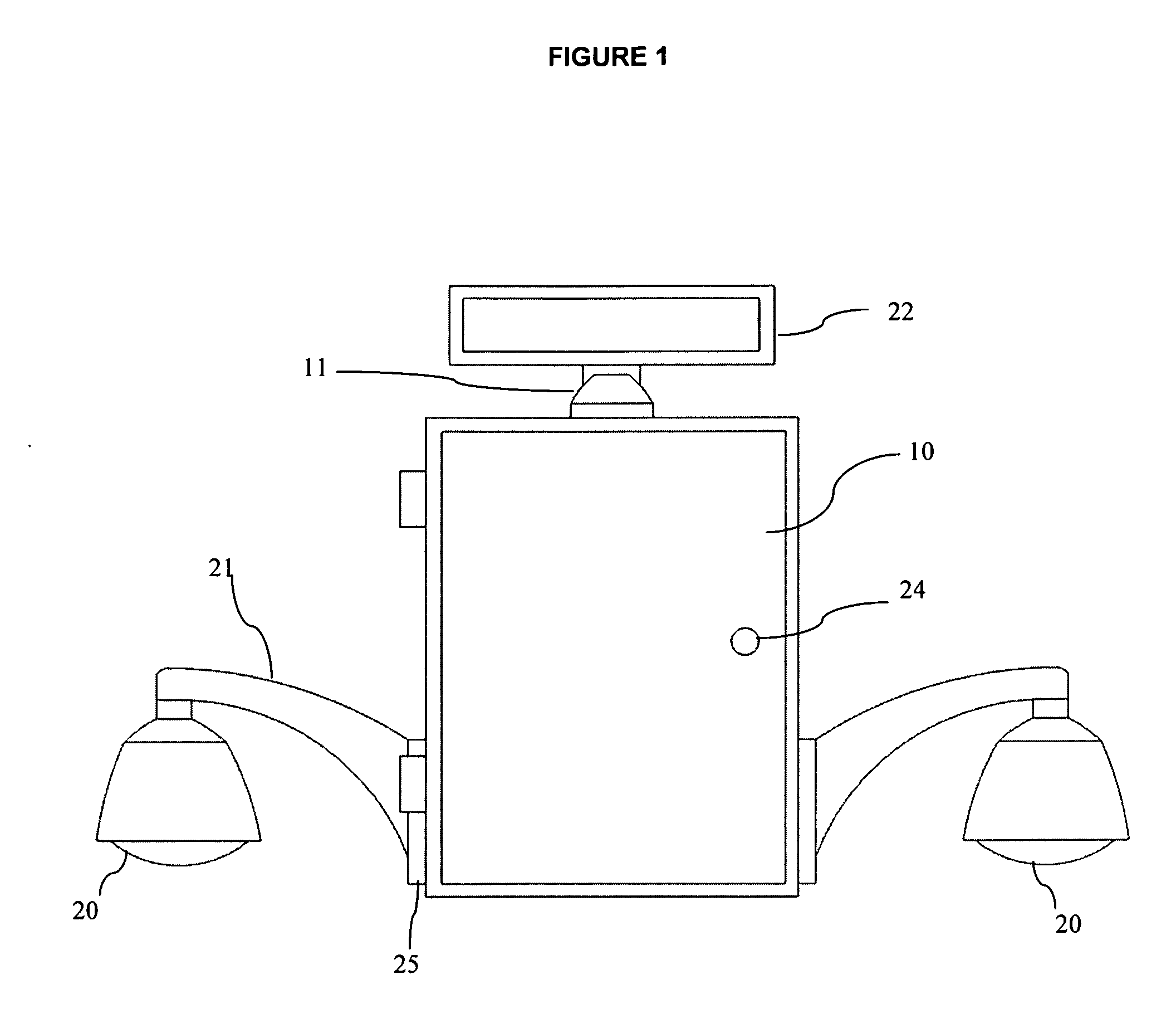
[0038]In the present embodiment of the invention the surveillance system has been designed and engineered to be a complete security system, contained in a compact enclosed cabinet that can be easily installed at any number of locations. The invention has been designed to remedy a wide variety of problems and deficiencies that exist with the current embodiments of surveillance systems in general. The claimed invention addresses the issues of having to run wiring and cable over long distances and the costs associated with this standard type of installation of a security system. The claimed invention also uses a plurality wireless communication devices, thus eliminating the need for hard wired communication links, and has the ability for two way communications with authorized users to report alarm activities, intrusions, system faults or any type of event that the user deems necessary to secure or survey an area. The claimed invention has the ability to perform a variety of functions i...


PUM


Abstract

A surveillance system that is comprised of an environmentally sealed metal cabinet enclosure consisting of high impact resistant metal, said enclosure consists of a metal back and having two equal metal sides and an equal top and bottom pieces that are framed and fastened in such a manner as to form a framed rectangular metal box style enclosure. A front mounted metal access door with two recessed metal hinges, a rubberized gasket to form a seal and an attached locking device and handle complete the cabinet enclosure. Side access ports of at least one per side, and generally being round in nature provide a side access point to the interior of the cabinet, said access ports provide a mounting point for the generally hollow camera mounting arm to be attached to each side of said cabinet. The said access ports allow wiring and cables to pass through the connected camera mounting arm to the interior of the cabinet, with said camera mounting arm ends being environmentally sealable, thus rendering the wiring and cable protected from the environment and secure from tampering or accidental damage. The cabinet contains and houses the various subsystem components consisting of, but not limited to, a video encoding device, communication equipment and various control systems for powering and controlling the plurality of pan, tilt and zoom cameras with analytic capabilities, sensor apparatus, various warning devices and having at least one, but not limited to one, power source providing power to the plurality of electronic devices. Secondly, a programmable LED digital message board is positioned and attached at or near the top of the cabinet to provide a highly visible visual warning that the area is under surveillance.

Description

TECHNICAL FIELD OF THE INVENTION[0001]The present invention relates to the field of video surveillance and security, wherein the surveillance requirements call for the installation of a permanent or long term surveillance presence.BACKGROUNDDescription of the Related Art[0002]The use of a variety of surveillance equipment, cameras and other electronic devices are well known in the art as a means of surveillance and monitoring activities at various events and locations.[0003]Often a video surveillance system is comprised of a single camera mounted to a structure and fixed on a single limited area of view, such as a door or entrance gate, and the video is then sent via cable to a single video monitor to observe the area, and may also be connected to some type of recording device to capture and record the video image. As the need for security and monitoring increases additional cameras and equipment may be added, these additions are often comprised of mismatched components requiring ad...

Claims


Application Information

Patent Timeline
Patent Type & Authority Applications(United States)
IPC IPC(8): H04N7/18
CPCG08B13/19608G08B13/1963H04N5/2259H04N5/2252G08B13/19663H04N23/51H04N23/58
Inventor LEFORT, JASON GUYROSS, LAURA CHRISTINE
Owner LEFORT JASON GUY
Why Eureka
Try Eureka