Fan system

a fan system and fan technology, applied in the direction of positive displacement liquid engine, piston pump, liquid fuel engine, etc., can solve the problems of increasing static pressure and reducing fan noise, and the conventional fan system has limitations in increasing static pressure and achieving the effect of low cos

Active Publication Date: 2009-11-26
SANYO DENKI CO LTD
View PDF7 Cites 20 Cited by
  • Summary
  • Abstract
  • Description
  • Claims
  • Application Information

AI Technical Summary

Benefits of technology

[0016]Preferably, the plurality of auxiliary duct blades are formed integrally with each of the first through fourth surfaces of the cylindrical body, extending in parallel to each other. With this configuration, the plurality of auxiliary duct blades can be designed easily.
[0017]When the n is an in...

Problems solved by technology

A conventional fan system, however, has limitations in increasing the static pressure r...

Method used


Image

  • Fan system
  • Fan system
  • Fan system

Examples


Embodiment Construction

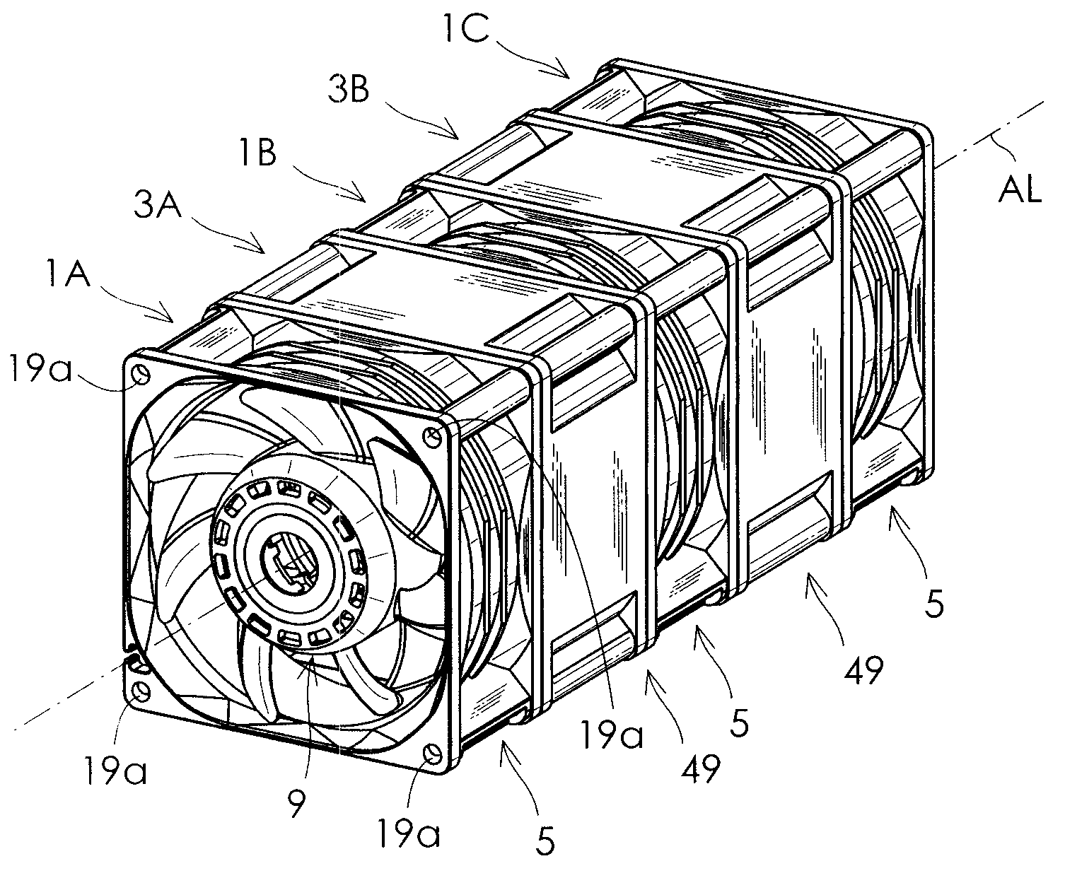
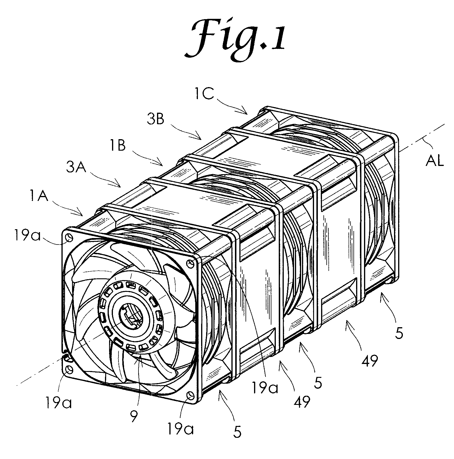
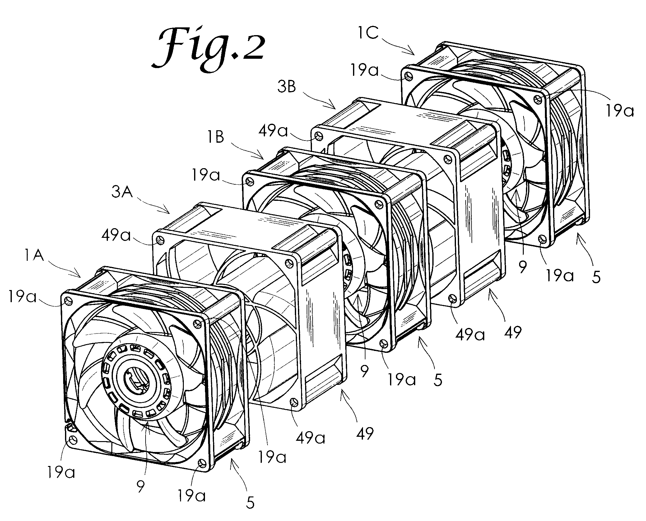
[0035]An embodiment of the present invention will be hereinafter described in detail with reference to the drawings. FIG. 1 is a perspective view of a fan system according to an embodiment of the present invention. FIG. 2 is an exploded perspective view of the fan system shown in FIG. 1. As shown in the figures, the fan system according to this embodiment includes n axial flow fans 1A to 1C (n is an integer of 2 or more, which is 3 in this embodiment), and n-1 (2 in this embodiment) ducts 3A and 3B, which are alternately disposed on the same axis AL. The axial flow fans 1A to 1C have the same structure, and the ducts 3A and 3B have the same structure. In the fan system according to this embodiment, air is flown in the direction from the axial flow fan 1A toward the axial flow fan 1C. For the duct 3A, thus, the axial flow fan 1A works as an axial flow fan disposed on the front side and the axial flow fan 1B works as an axial flow fan disposed on the rear side. For the duct 3B, the ax...


PUM


Abstract

A fan system with enhanced air flow-static pressure characteristics and reduced fan noise compared to the related art is provided. The number of duct blades of a duct is the same as the number of stationary blades of an axial flow fan located in front of the duct, and the duct blades correspond to the stationary blades respectively. An end surface of a rear end portion of each stationary blade and an end surface of a front portion of a duct blade corresponding to the stationary blade have the same shape, and they align together and contact each other to form one composite stationary blade, with a discharge port of each axial flow fan communicating with an inlet port of a duct housing located behind the axial flow fan.

Description

BACKGROUND OF THE INVENTION[0001]1. Field of the Invention[0002]The present invention relates to a fan system including axial flow fans and ducts interposed therebetween.[0003]2. Description of the Related Art[0004]Japanese Patent Application Publication No. 2007-263004 (JP2007-263004A) discloses a fan system including a front axial flow fan, a rear axial flow fan, and a duct interposed between the axial flow fans. The axial flow fans each include a cylindrical housing body formed with an air channel having a suction port and a discharge port. The housing body includes four support portions that connect a motor and the housing body in the discharge port. The duct has a cylindrical duct housing. The duct housing includes eight duct blades disposed at intervals in a circumferential direction inside the duct housing and extending radially. The duct blades have the shape of a flat plate extending straight.[0005]A conventional fan system, however, has limitations in increasing the static...

Claims


Application Information

Patent Timeline
IPC IPC(8): F04D29/00F04B17/00F04D29/40
CPCF04D19/007F04D29/542F04D25/0613F04D29/544
Inventor MIYABARA, YOSHINORIWATANABE, JIROKURIBAYASHI, HIROMITSU
Owner SANYO DENKI CO LTD
Why Eureka
Try Eureka