
Method and injection molding machine having a modular structure

Inactive Publication Date: 2009-11-26
NETABTAL MASCHEN
View PDF3 Cites 7 Cited by
  • Summary
  • Abstract
  • Description
  • Claims
  • Application Information

AI Technical Summary

Benefits of technology

[0044]In this way, the protective cover for the entire machine is also constructed according to the modular concept and can be selected from standardized parts. The

Problems solved by technology

Handling and logistics are then also complex, because the same company must process several concepts.
Such longitudinal connections would be unable to withstand, when transported as a single piece, handling, such as lifting with a crane, or moving or placing the machine on uneven support surfaces.
Upon closer scrutiny, some expenses are uneconomical.
There is a risk for a company to limit itself to only a single type or a standard line of a sin

Method used


Image

  • Method and injection molding machine having a modular structure
  • Method and injection molding machine having a modular structure
  • Method and injection molding machine having a modular structure

Examples


Example

[0047]The invention will now be described in more detail with reference to several exemplary embodiments:

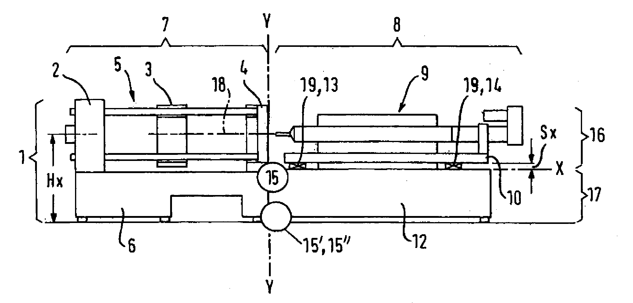
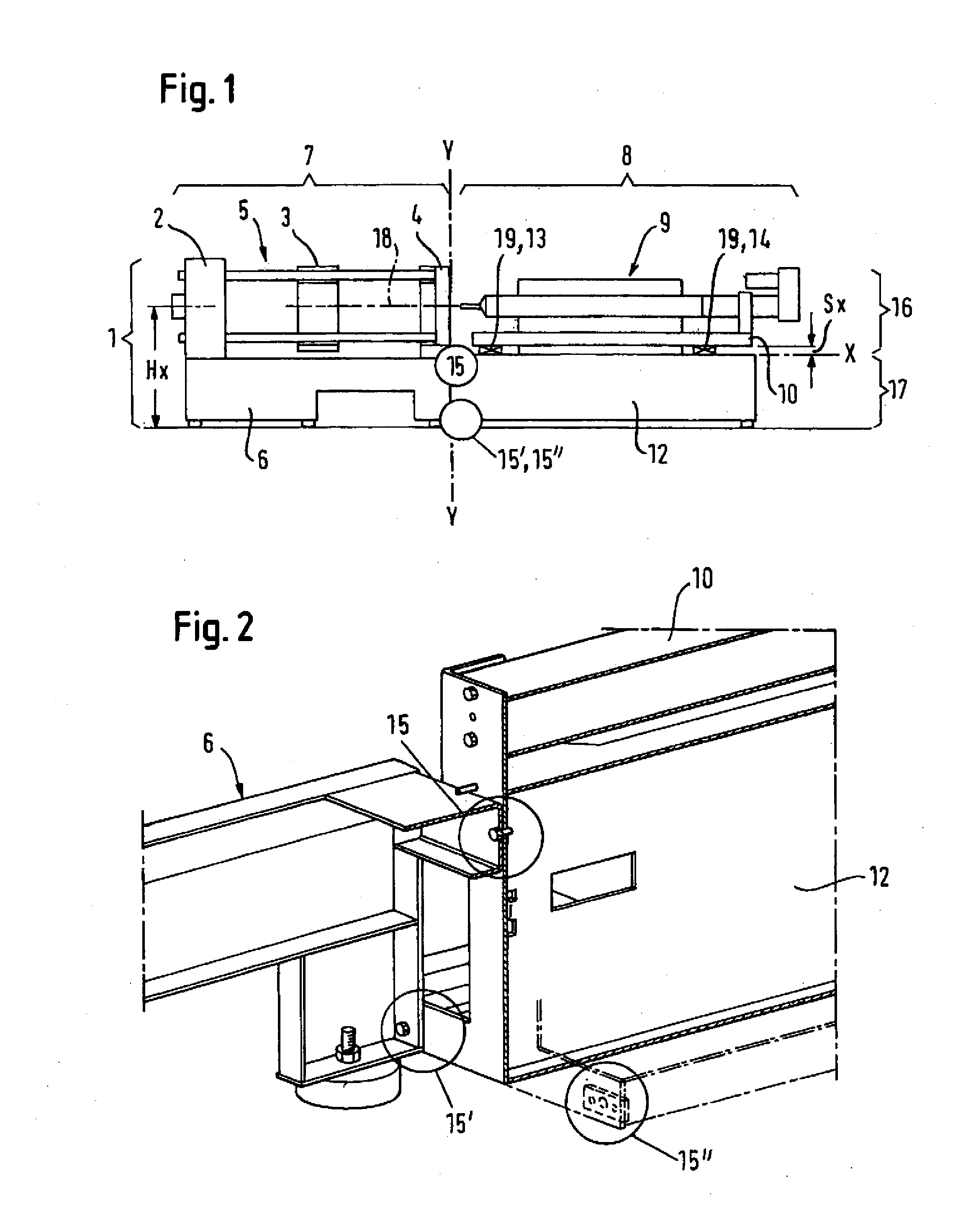
[0048]FIG. 1 shows an entire injection molding machine with the mold clamping side and the injection unit side, which can be separated or assembled via the axis Y-Y;

[0049]FIG. 2 shows a cross-sectional view with the assembly and / or coupling interfaces between the mold clamping bed and the injection module substructure;

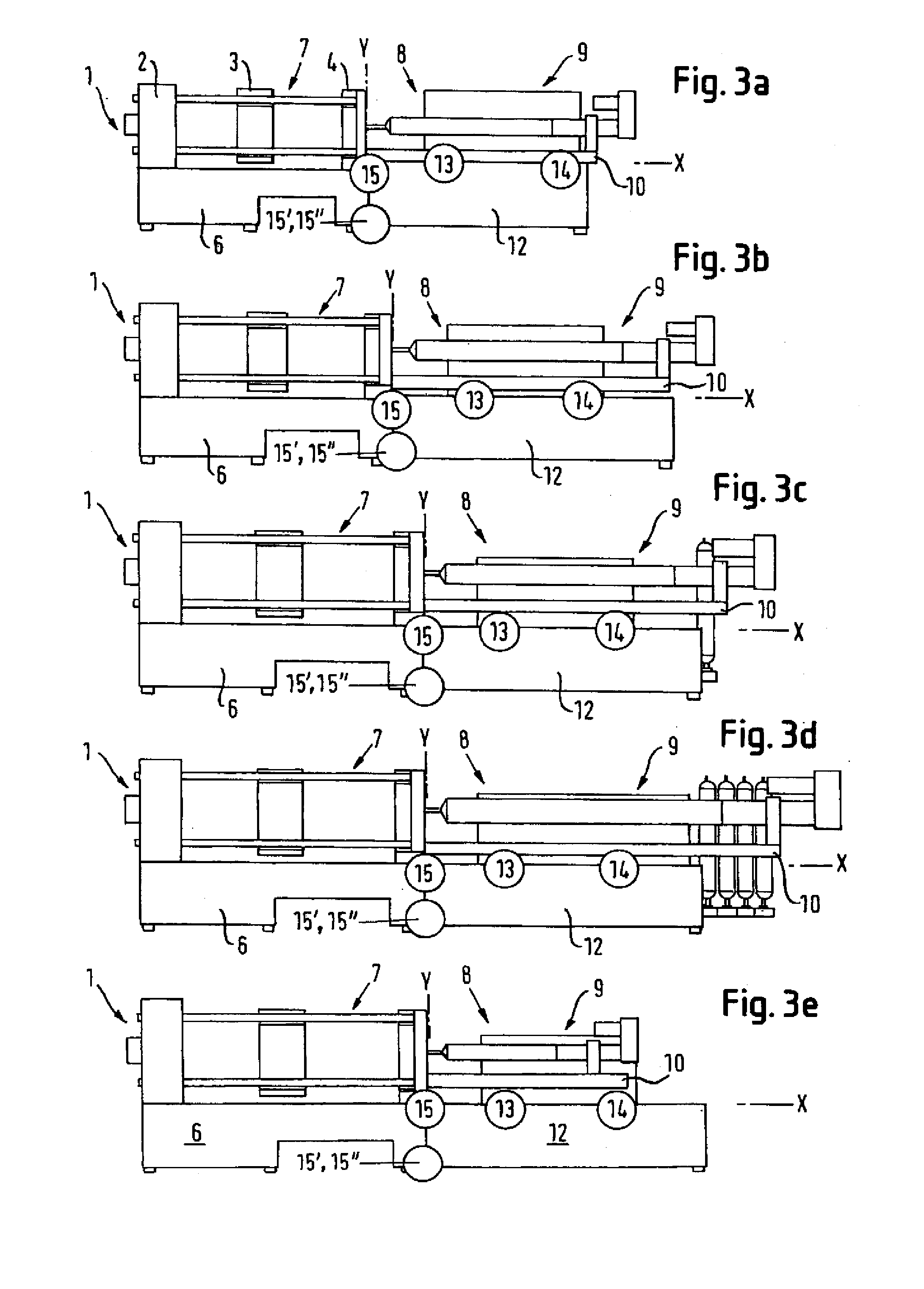
[0050]FIGS. 3a to 3e show five different injection molding machines with modules from three lines of modules;

[0051]FIG. 4 shows the mold clamping side, designed as mold clamping module with mold clamping bed;

[0052]FIG. 5 shows the platen on the injection-nozzle side with standardized tie rod interfaces and corresponding coupling interfaces for the injection unit;

[0053]FIG. 6 shows a complete injection unit module with a support element or support tube;

[0054]FIG. 7 shows the coupling interfaces between the support tube as injection unit module and the injection modul...


PUM

PropertyMeasurementUnit
Fractionaaaaaaaaaa
Massaaaaaaaaaa
Forceaaaaaaaaaa

Abstract

The invention relates to a method and an injection-molding machine with modular structure. In the solution proposed, to optimize logistics, in particular transport, the design and the construction of at least the mould-clamping mechanism side (7) and the injection system side (8) of the machine are modular. There are central unitary mounting and coupling interfaces (13 and 14 or 15, 15′, 15′) by way of which a mould-clamping module (1), a system module (16) and a drive module (17) are connected. The three modules can be selected freely from appropriate ranges of mould-clamping modules and system modules and drive modules.

Description

TECHNICAL FIELD[0001]The invention relates to a method for logistics, the configuration and the structure of injection molding machines at the machine manufacturer, in particular for the production and the transport of injection molding machines, and to an injection molding machine having a two-part structure with an injection unit side.STATE OF THE ART[0002]Two concepts have been established with injection molding machines. For practical and logistic reasons, these concepts are based on the total weight of the machines. Injection molding machines with a closing force of up to about 400 tons have a weight of less than 25 tons. They are manufactured as one piece and can be transported in large containers from the manufacturer to the operator of the machines over any distance as a single piece, i.e., undivided. Handling can be accomplished by different means, for example cranes and air cushions, with which loading can be performed without problem. Typically, machines with a closing fo...

Claims


Application Information

Patent Timeline
IPC IPC(8): B29C45/10B29C45/03
CPCB29C45/03B29C45/1761B29C45/46Y10T29/49826B29C2045/1765B29C2045/1767B29C45/64
Inventor WENZIN, PLACIJENNY, DANIELWEINMANN, ROBERT
Owner NETABTAL MASCHEN
Learn More