Orthodontic brackets and appliances and methods of making and using orthodontic brackets

a technology for applied in the field of orthodontic brackets and appliances, can solve the problems of difficult handling and application of brackets, small spatial clearance of ligating brackets, and certain recognition of traditional ligatures, and achieve the effect of small cross-sectional area

Inactive Publication Date: 2009-11-26
ORMCO CORP
View PDF54 Cites 26 Cited by
  • Summary
  • Abstract
  • Description
  • Claims
  • Application Information

AI Technical Summary

Problems solved by technology

However, traditional ligatures have certain recognized disadvantages, such as difficulties in handling and application to the brackets.
In the absence of a ligature, however, an archwire installed in an archwire slot of a self-ligating bracket may experience a small amount of spatial clearance relative to the walls bounding the archwire slot.
During corrective orthodontic treatments, orthodontic brackets applied to anterior teeth tend to experience a loss of torque control.
However, a significant disadvantage of investment casting is that alphanumeric characters cannot be integrated into the identification marking because fine details cannot be transferred from the complementary mark on the casting mold.
A significant disadvantage of such rudimentary identification markings is that the doctor must interpret what the various symbols mean in relation to the bracket type.
However, a significant disadvantage of laser etching is that the identification markings are scribed in the bracket body after manufacture, which entails additional process steps and expense.
However, a significant disadvantage of such temporary color identification dots is that they are designed to dissolve in the environment presented inside the patient's mouth.
Consequently, the identification of the bracket type is completely lost shortly after the bracket is deployed in the patient's mouth.
Another significant disadvantage of temporary color identification markings is that the doctor must interpret what the color identification dots mean in relation to the bracket type.
However, the bent end of the protruding shank may present an irritant for the patient.
Removal is difficult because the bent end is in close proximity to the bracket body, which limits the space available for a cutting implement.

Method used


Image

  • Orthodontic brackets and appliances and methods of making and using orthodontic brackets
  • Orthodontic brackets and appliances and methods of making and using orthodontic brackets
  • Orthodontic brackets and appliances and methods of making and using orthodontic brackets

Examples


Embodiment Construction

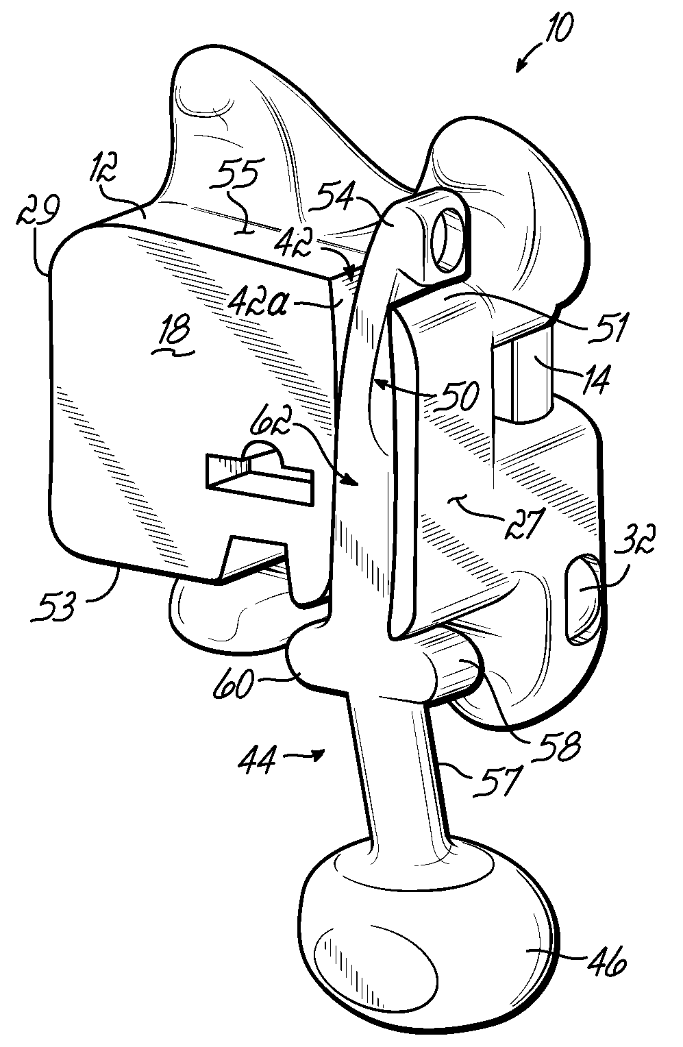
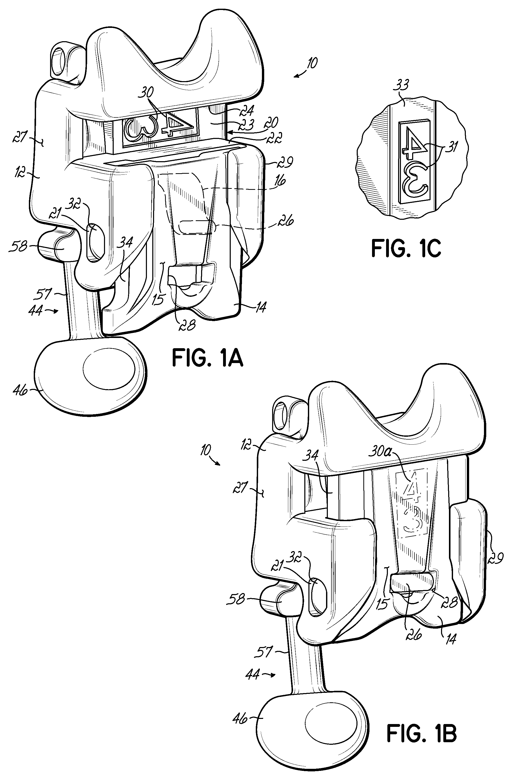
[0029]Referring to FIGS. 1A and 1B, an orthodontic bracket 10 comprises a self-ligating bracket for use in corrective orthodontic treatments that improve a patient's occlusion. The orthodontic bracket 10, which may be constructed from a metal, a ceramic, a plastic, or a composite construction of multiple types of these materials, includes a bracket body 12 having an archwire slot 20, a movable ligating cover 14 movable relative to the archwire slot 20 of the bracket body 12 in an occlusal-gingival direction between opened and closed positions, and a spring arm 16 that latches the ligating cover 14 in the closed position. When the ligating cover 14 is in the opened position shown in FIG. 1A, the archwire slot 20 is accessible for inserting an archwire 25 (FIG. 3). When the ligating cover 14 is in the closed position shown in FIG. 1B, access to archwire slot 20 is blocked or otherwise occluded.

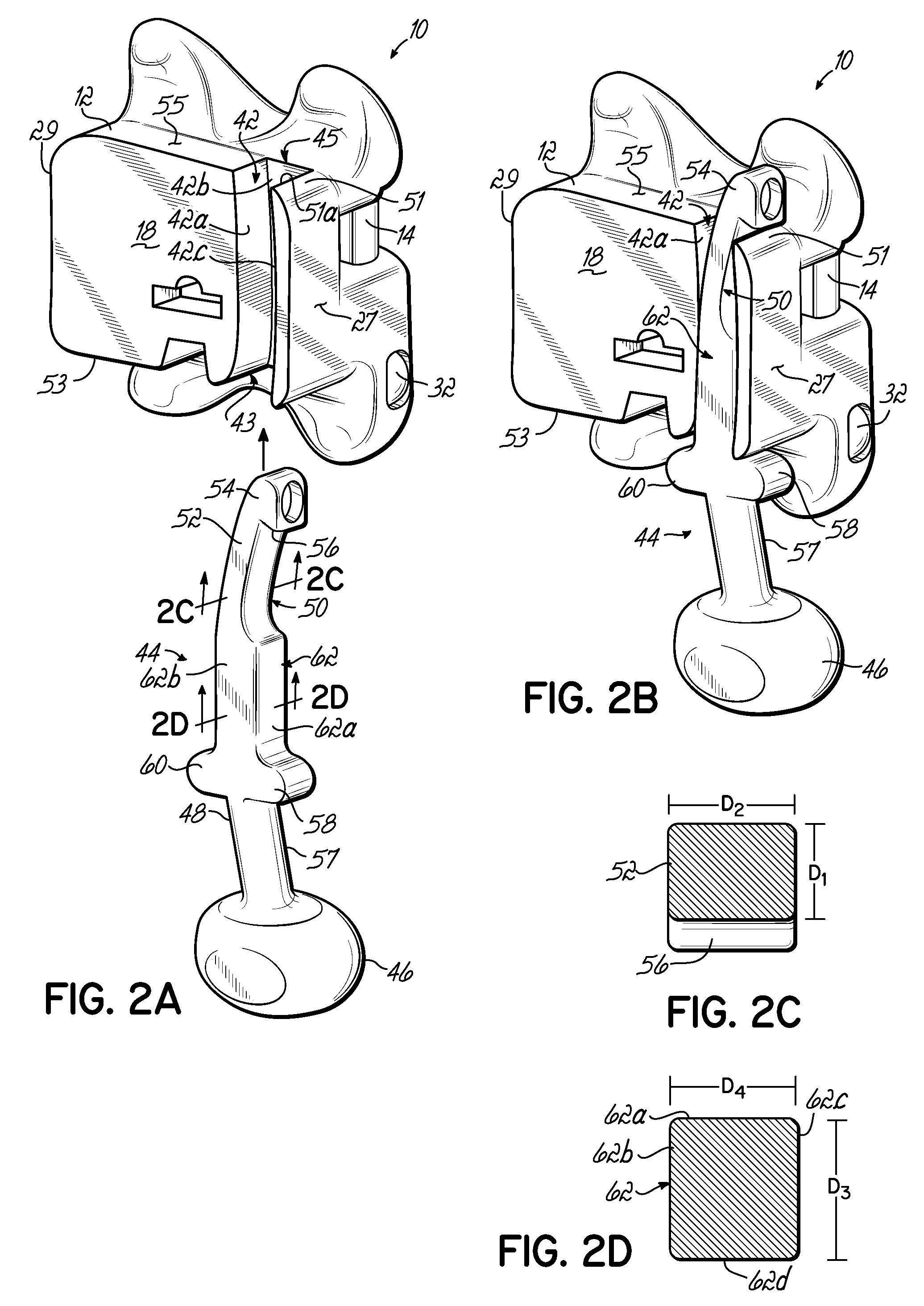
[0030]A bonding base 18 (FIG. 2A) on the bracket body 12 is used to secure the orthodontic b...


PUM


Abstract

Orthodontic brackets and appliances, and methods of making and using orthodontic brackets. The orthodontic bracket may include a molded identification marking including at least one alphanumeric character disposed on a visible surface. A kit of self-ligating orthodontic brackets may be provided that includes individual brackets of different archwire slot widths for attachment to anterior and posterior teeth during a corrective orthodontic treatment. An appliance or auxiliary may be provided that includes a spring-loaded latch operative to secure the appliance to an orthodontic bracket.

Description

CROSS-REFERENCE TO RELATED APPLICATIONS[0001]This application is a divisional of application Ser. No. 11 / 381,856, filed May 5, 2006, which claims the benefit of U.S. Provisional Application No. 60 / 683,023 filed on May 20, 2005, the disclosure of each of which is hereby incorporated by reference herein in its entirety.FIELD OF THE INVENTION[0002]The invention relates generally to orthodontic brackets and appliances for use with orthodontic brackets.BACKGROUND OF THE INVENTION[0003]Orthodontic brackets represent a principal component of all corrective orthodontic treatments devoted to improving a patient's occlusion. In conventional corrective orthodontic treatments, brackets are affixed to the patient's teeth and an archwire is threaded through a slot of each bracket. The archwire applies corrective forces that coerce the teeth to move to orthodontically correct positions. Traditional ligatures, such as small elastomeric O-rings or fine metal wires, are employed to retain the archwir...

Claims


Application Information

Patent Timeline
Patent Type & Authority Applications(United States)
IPC IPC(8): A61C7/30A61C7/28
CPCA61C7/287A61C7/12
Inventor ODA, TODD I.
Owner ORMCO CORP
Why Eureka
Try Eureka