
System and method visible surface determination in computer graphics using interval analysis

a visible surface and interval analysis technology, applied in the field of computer imaging or graphics, can solve the problems of reconstructed images using conventional point-sampling, inability to compute accurately and deterministic, and numerical instability of the intersection between a point-sampling ray and the primitive,

Active Publication Date: 2007-07-31
SUNFISH STUDIO
View PDF5 Cites 35 Cited by
  • Summary
  • Abstract
  • Description
  • Claims
  • Application Information

AI Technical Summary

Benefits of technology

"The present invention provides a system and method for reconstructing digital images using interval analysis instead of traditional point sampling. This approach allows for accurate and deterministic computation of the visible solution set of a pixel, and the color of that pixel can be determined to a user-specified level of detail. The system is scalable and efficient for both still and video images, and can be used in a network grid or in a graphics accelerator for improved performance. The system also allows for automatic adaptive resolution based on the fidelity of the rendering machine, and provides efficient data compaction for transmission over limited bandwidth connections. The system can casually seek edges of objects or transitional areas, and the convergence to the proper visible solution set of a pixel is a deterministic operation which exhibits quadratic convergence. The system can also compute tight bounds on the visible solution set of a pixel for each dimension that is specified, and integrate the visible solution set over the hemisphere for each dimension that is specified to compute global illumination effects."

Problems solved by technology

Most modern ray tracing algorithms only support geometric primitives of a low degree such as planes, triangles, spheres, and quadrics because the methods commonly used to find the visible point of intersection between a point-sampling ray and the primitive are numerically unstable for higher degree functions.
Moreover, because it has been heretofore impossible to compute in an accurate and deterministic manner the visible solution set of a pixel using traditional point-sampling techniques, undesirable aliasing must appear on reconstructed images using conventional point-sampling.

Method used


Image

  • System and method visible surface determination in computer graphics using interval analysis
  • System and method visible surface determination in computer graphics using interval analysis
  • System and method visible surface determination in computer graphics using interval analysis

Examples


Embodiment Construction

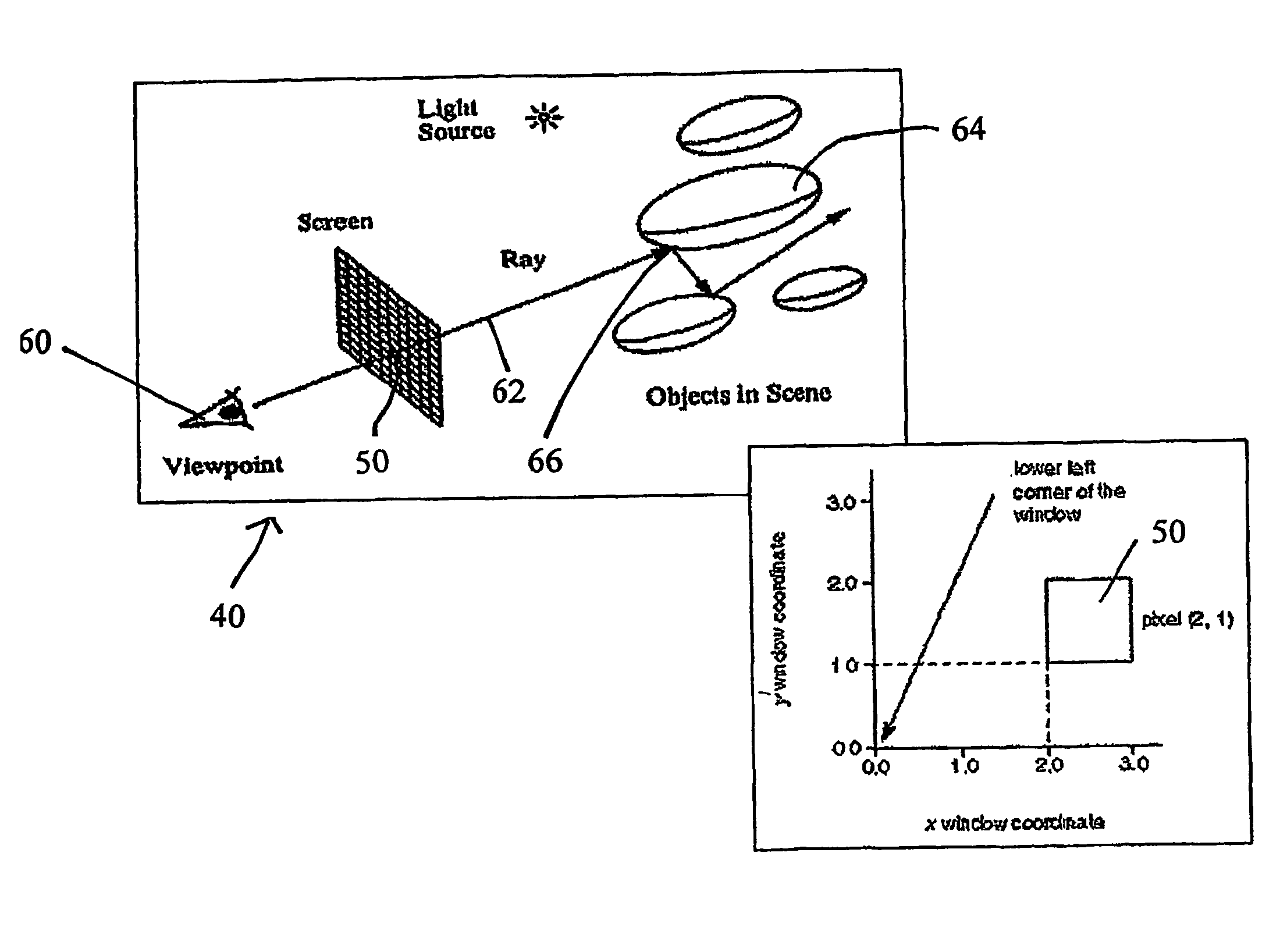
[0037]The present invention abandons existing point sampling techniques, and instead provides a system and attendant methodology for reconstructing two-dimensional digital images of a three dimensional digital representation of a visual scene, a process referred to as rendering, so as to photorealistically synthesize images. In furtherance of detailed invention development, a rendering framework is preliminarily outlined.

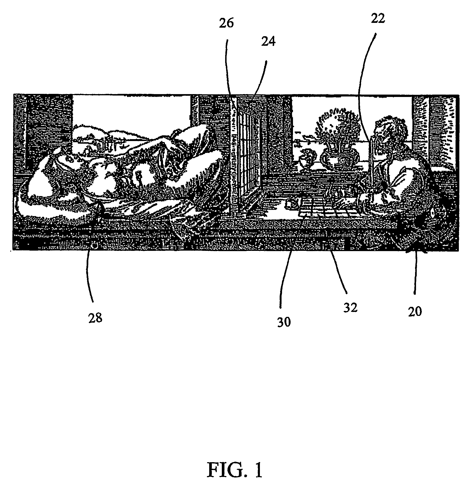
[0038]FIG. 1 shows a classic example of how a renaissance artist uses the well-known grid technique to translate real world images into two-dimensional drawings. An artist 20 uses a stick 22 as the reference point for the artist's viewing position. The artist 20 looks through the cells 24 created by a rectangular grid of twine 26 into a scene 28 behind the grid. A drawing paper 30 on which the artist 20 will render a two-dimensional representation of the scene 28 is divided into the same number of rectangular cells 32 as there are cells 24. The artist carefully copi...


PUM


Abstract

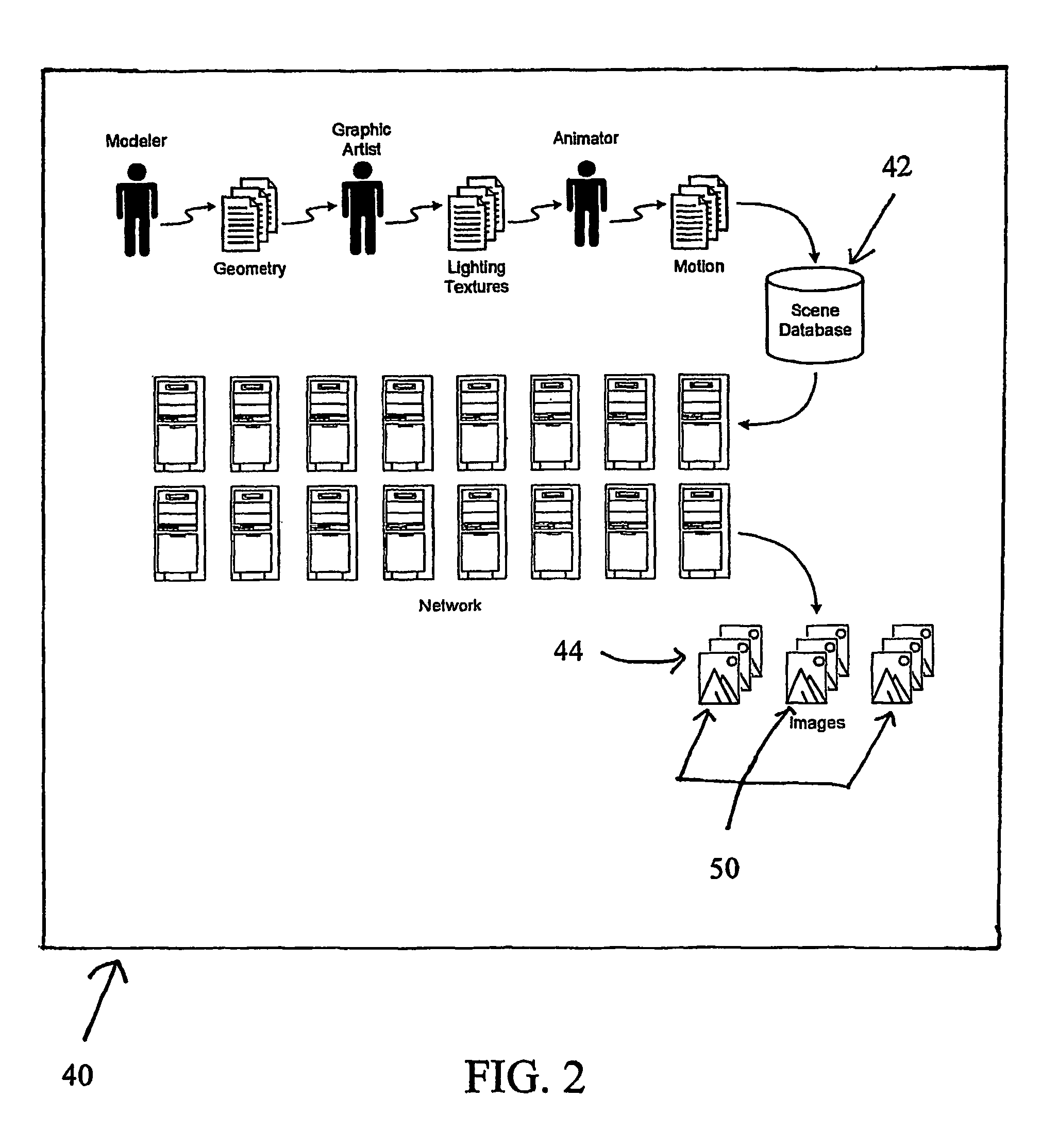
A system (40) is provided for visible surface determination in furtherance of photorealistic rendering in a computer graphics environment. The system includes a scene database (42) and a processor, visual characteristics of objects of an image frame (44) of a scene of the scene database (42) are delimited as geometric primitive. The processor, for executing an interval analysis, to a user degree of certainty, accurately and deterministically ascertains a visible solution set of an area not exceeding a pixel dimension for a pixel of an array of pixels (50) that form said image frame (44).

Description

[0001]This is a regular application filed under 35 U.S.C. §111(a) claiming priority under 35 U.S.C. §119(e) (1), of provisional application Ser. No. 60 / 426,763, having a filing date of Nov. 15, 2002.TECHNICAL FIELD[0002]The present invention generally relates to computer imaging or graphics, more particularly, to the field of photorealistic image synthesis utilizing interval-based techniques for integrating digital scene information in furtherance of constructing and / or reconstructing an image of the digital scene, and / or the construction of an image based solely on mathematical formulae.BACKGROUND OF THE INVENTION[0003]Photorealism for computer-generated scenes, that is to say, the production of a computer-generated scene that is indistinguishable from a photograph of the actual scene, as for instance, the elimination of aliasing, remains the “holy grail” for computer graphic artisans. So much so that Jim Blinn has proclaimed: “Nobody will ever solve the antialiasing problem,” emph...

Claims


Application Information

Patent Timeline
Patent Type & Authority Patents(United States)
IPC IPC(8): G06T15/40G06FG06T15/06G06T15/50G06T15/80
CPCG06T15/06G06T15/50G06T15/80G06T2200/12
Inventor HAYES, NATHAN T.SCHMIDT, DAVID R.
Owner SUNFISH STUDIO
Learn More