Touch-control structure for a flexible display device

a flexible display device and touch control technology, applied in the direction of instruments, computing, electric digital data processing, etc., can solve the problems of easy deformation with external forces, damage, and difficulty in applying touch control functions to existing flexible display devices, and achieve the effect of simple structure and manufacturing process, not degrading image brightness

Active Publication Date: 2010-07-08
E INK HLDG INC
View PDF16 Cites 38 Cited by
  • Summary
  • Abstract
  • Description
  • Claims
  • Application Information

AI Technical Summary

Benefits of technology

[0011]The primary objective of this invention is to provide a touch-control structure for a flexible display device. The touch-control structure has a simple structure and manufacturing process, and will not degrade the image brightness of the flexible display device.

Problems solved by technology

However, as the display device becomes thinner, the thin profile provides relatively insufficient structural strength.
In addition, the substrate of the conventional thin-profile display device, such as a liquid crystal display device, mainly consists of glass, which can be easily deformed with external forces and damaged accordingly.
However, it is still difficult to apply a touch-control function to an existing flexible display device with these products.
However, the excessive heat energy of this high temperature will damage the flexible substrate, which commonly utilizes organic plastic material, and further damage the touch-control function.
On the contrary, forming the transparent conductive film with a relatively low processing temperature tends to degrade the conducting property and transparency of the transparent conductive film.
Furthermore, it would be difficult for the transparent conductive film to adhere onto the substrate when formed with low temperature and would further cause the film to peel.
As a result, it would be difficult to form the transparent conductive film of good quality on the flexible substrate, which in turn makes it difficult to raise the yield rate of the product utilizing the flexible substrate.
However, it would be difficult to overcome the problem when applying the touch-control film of the conventional arrangement to non-self-illuminating display technologies which utilize environmental light sources, such as electronic paper utilizing electronic-ink.

Method used


Image

  • Touch-control structure for a flexible display device
  • Touch-control structure for a flexible display device
  • Touch-control structure for a flexible display device

Examples


Embodiment Construction

[0022]In the following description, this invention will be explained with reference to embodiments thereof, which provide a touch-control structure for a flexible display device. Descriptions of these embodiments are only for illustration rather than limitation. It should be appreciated that in the following embodiments and the attached drawings, elements indirectly related to this invention are omitted from depiction, and dimensional relationships among individual elements depicted in the drawings are only for facilitating the understanding of the invention rather than limiting the actual dimension.

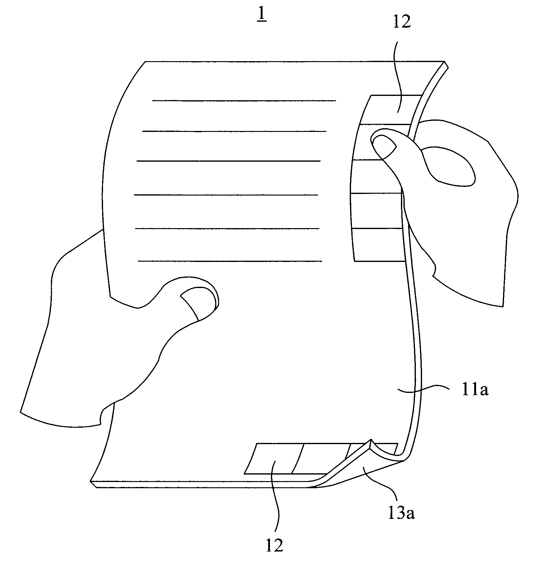
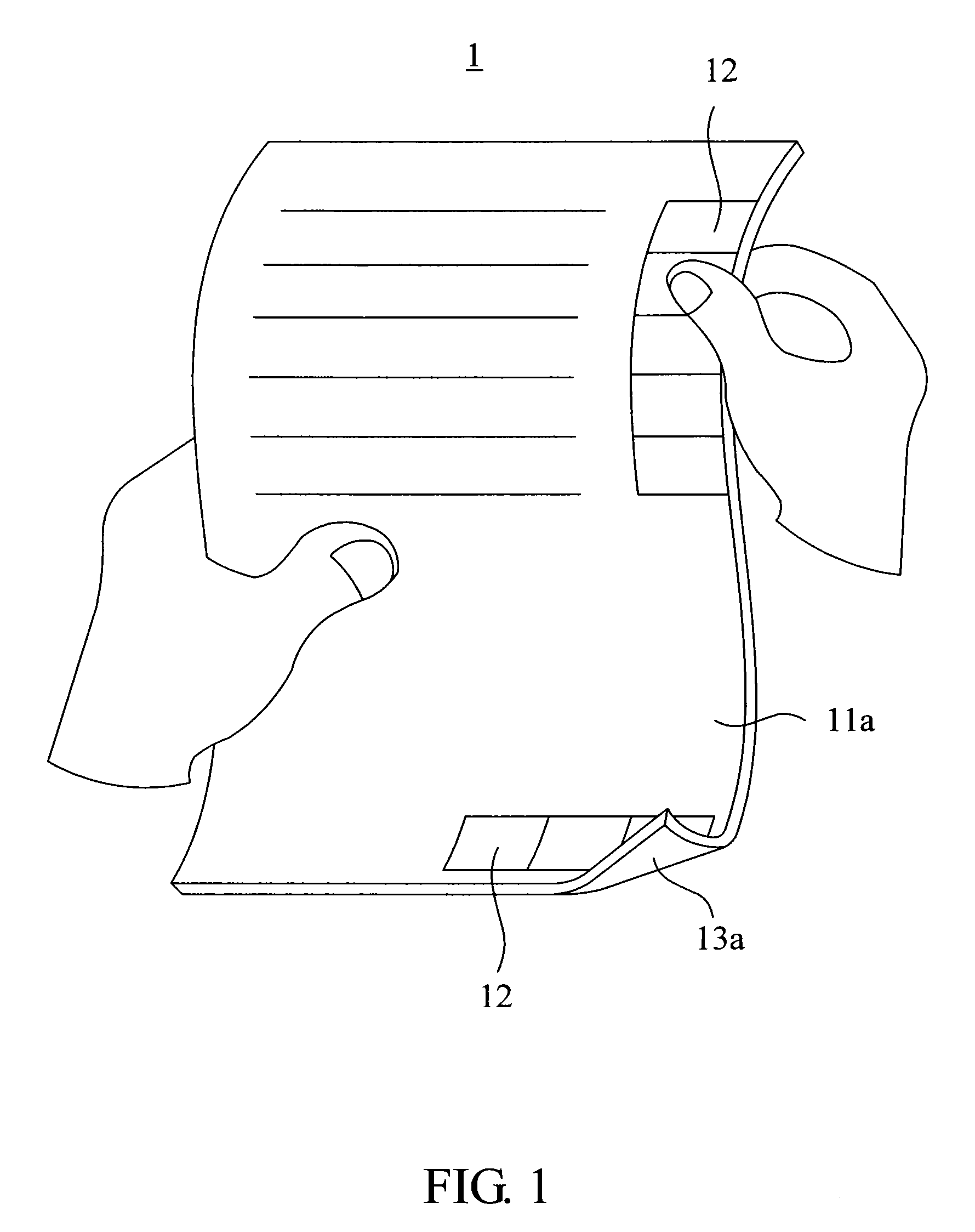
[0023]FIG. 1 illustrates the flexible display device 1 which utilizes the touch-control structure of this invention. The flexible display device 1 can be held like a newspaper or book for the user to read and has a visible surface 11a, at least one menu display area 12, an operating contact surface 13a and a control module circuit 19. The menu display area 12 is located on at least one s...


PUM


Abstract

A touch-control structure for a flexible display device is provided. The touch-control structure comprises a flexible display panel, at least one menu display area, a touch film and at least one sensing element. The flexible display panel comprises a visible surface. The menu display area is located on at least one side of the visible surface. The touch film comprises a first flexible substrate and an operating contact surface. The visible surface and the operating contact surface are disposed on the two opposite ends of the touch structure respectively. The sensing element is disposed on at least one side of the first flexible substrate corresponding to the menu display area.

Description

[0001]This application claims the benefit of priority based on Taiwan Patent Application No. 098100458 filed on Jan. 8, 2009, the disclosures of which are incorporated by reference herein in their entirety.CROSS-REFERENCES TO RELATED APPLICATIONS[0002]Not applicable.BACKGROUND OF THE INVENTION[0003]1. Field of the Invention[0004]The present invention relates to a touch-control structure. More particularly, the present invention relates to a touch-control structure for use in a flexible display device.[0005]2. Descriptions of the Related Art[0006]With the advancement of science and technology, display devices have become thinner and more lightweight to reduce the occupying space and weight. In the mean time, with the development of the user interface, the touch panel has become a very common input interface. However, as the display device becomes thinner, the thin profile provides relatively insufficient structural strength. In addition, the substrate of the conventional thin-profile...

Claims


Application Information

Patent Timeline
Patent Type & Authority Applications(United States)
IPC IPC(8): G06F3/041
CPCG06F3/041G06F3/0414G06F3/045G06F2203/04102G06F1/1643G06F1/1652G06F3/0412G06F3/0482
Inventor CHUANG, KAI-CHENG
Owner E INK HLDG INC
Why Eureka
Try Eureka