Real time simulating method and system

Active Publication Date: 2009-11-26
ISRAEL AEROSPACE IND +1
View PDF14 Cites 10 Cited by
  • Summary
  • Abstract
  • Description
  • Claims
  • Application Information

AI Technical Summary

Benefits of technology

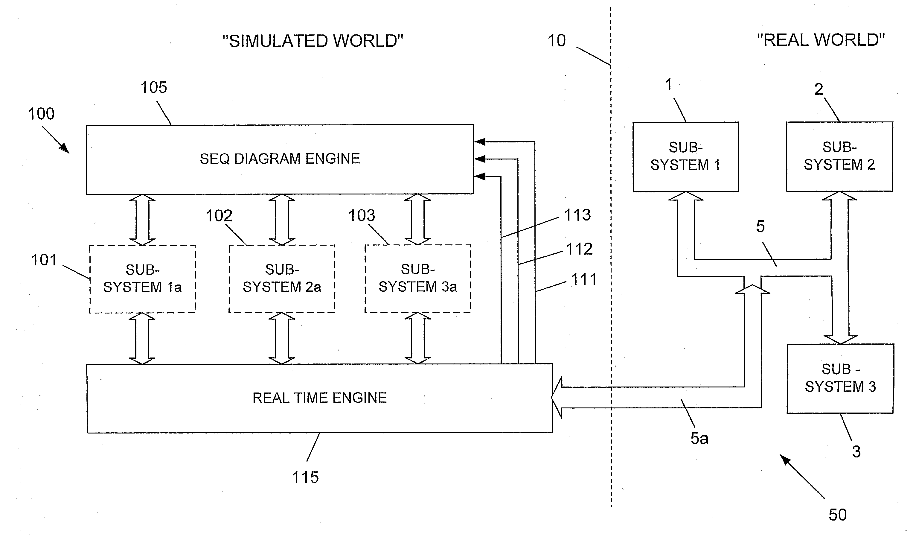
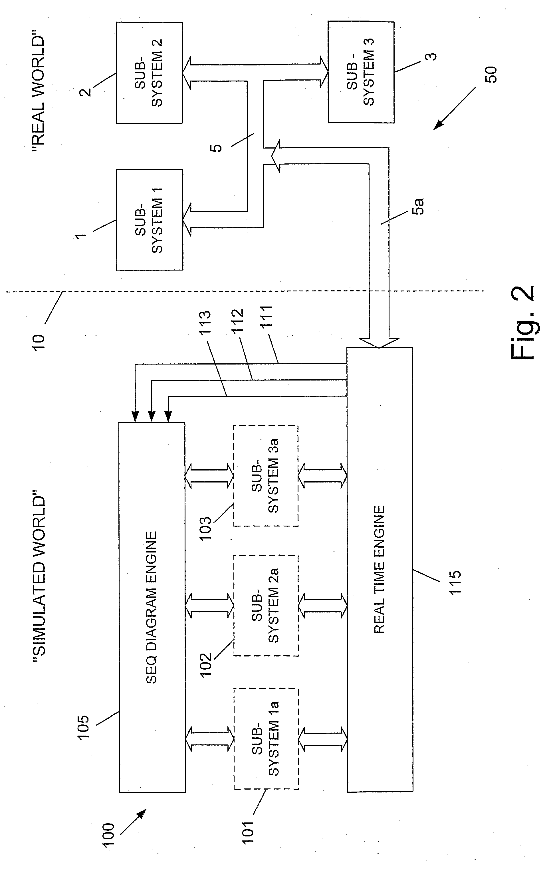
[0014]The present invention relates to a method for alternately simulating sub-systems of a tested real system, comprising the steps of: (a) producing a sequence diagram defining the intercommunication of messages between the various sub-systems of the real system in terms of at least time, message name, issuing sub-system, and destination sub-system; (b) whenever there is a need to test one or more real sub-systems of the system, activating said sequence diagram, while eliminating those messages relating to existing sub-systems, and maintaining all those messages rel

Problems solved by technology

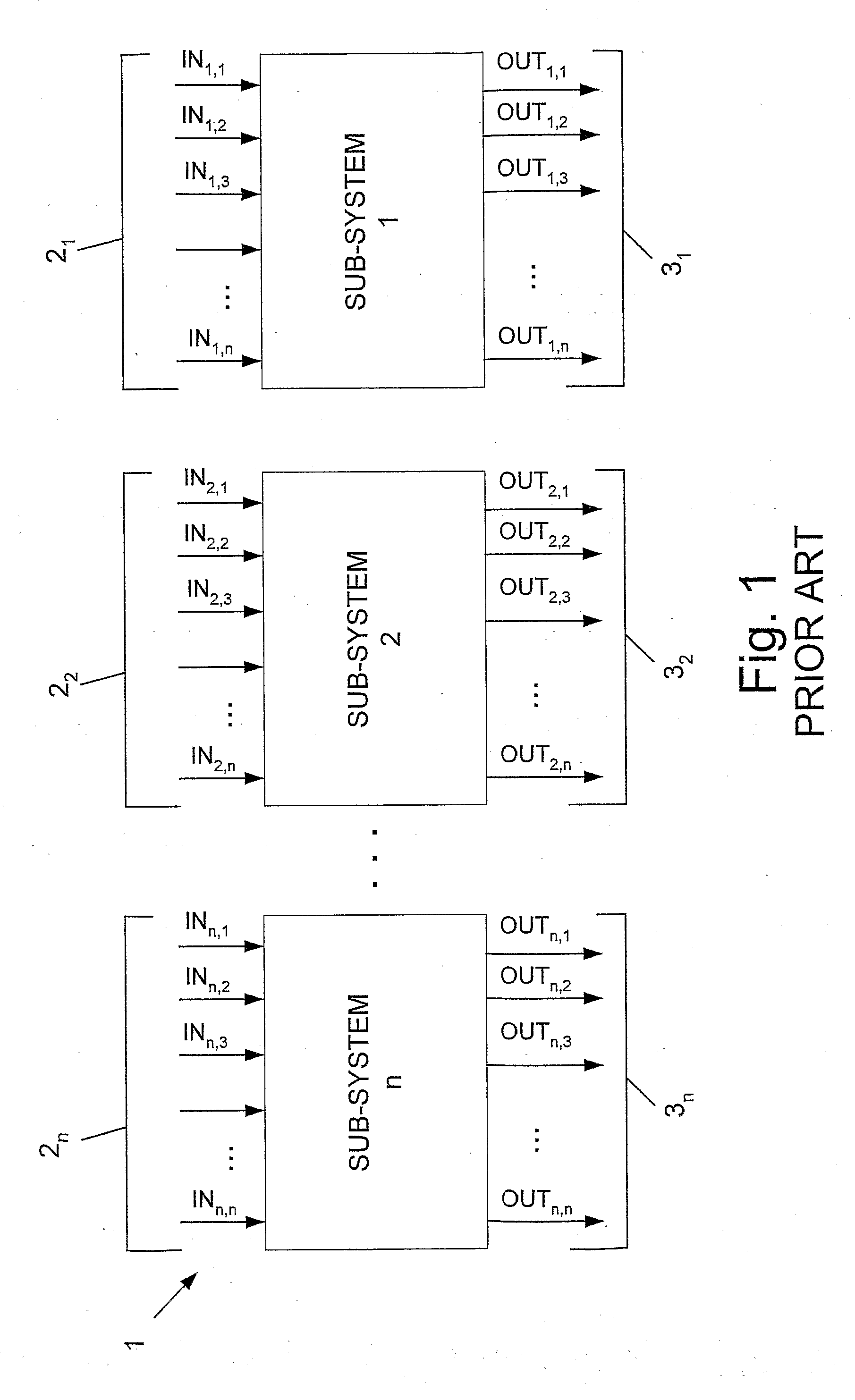
The process of developing a system which comprises plurality of sub-systems is generally very long and complicated.
However, naturally the development of all the separate real sub-systems does not progress at the same speed, and there are many cases in which one sub-system cannot be tested until the development of another sub-system sufficiently progresses to a desired stage.
Such sce

Method used


Image

  • Real time simulating method and system
  • Real time simulating method and system
  • Real time simulating method and system

Examples


example

[0048]FIG. 5 illustrates an exemplary simplified sequence diagram for a missile system, which can be used according to the present invention. The sequence diagram was produced using UML2 language. The missile system comprises one user (an Attack Commander) and three sub-systems, as follows: a Control Center, a Launcher, and a Missile. Each of the above sub-systems and even the user can be simulated, while testing the other real sub-systems. As said, only the messages of missing sub-systems are issued and thereafter conveyed to the “real world”, while all the others messages relating to existing and tested sub-systems are eliminated. Now, assuming that the Control Center and Missile are real, while the Launcher is simulated, the operation is as follows: The operation of the system begins by issuing a “Prepare” message by the real Control Center sub-system to the simulated Launcher sub-system unit. This issuing of said message depends (i.e., conditioned) on a false status of the messa...


PUM


Abstract

System for simulating one or more sub-systems of a tested system includes: (a) a sequence diagram storage and engine unit containing a predefined sequence diagram defining the intercommunication of messages between the various sub-systems of a real system in terms of at least time, message name, issuing sub-system, and destination sub-system. An indicator indicates to said sequence diagram storage and engine unit, those missing sub-systems, which have to be simulated. A receiver within said sequence diagram storage and engine unit receives an activation signal for the sequence diagram, and for eliminating all those messages in the sequence diagram relating to non-missing sub-systems, while maintaining those messages relating to missing sub-systems. One or more simulated sub-system units, each contain a domain of predefined output messages in appropriate format that can be issued by the simulated sub-system unit, and predefined input messages in appropriate format that can be received by the simulated sub-system unit, both domains being essentially identical to those of the corresponding real sub-systems of the system. A real time engine activates the sequence diagram, for receiving messages relating to missing sub-systems from one or more of the simulated sub-systems units, for introducing in real time the received messages on a bus leading to the real sub-systems, and for receiving messages issued by the real sub-systems and conveying them in real time to the simulated sub-system units.

Description

FIELD OF THE INVENTION[0001]The field of the invention generally relates to a method for simulating in real time, a system which comprises a plurality of sub-systems, that perform intercommunication one with the others.BACKGROUND OF THE INVENTION[0002]The process of developing a system which comprises plurality of sub-systems is generally very long and complicated. Several separate groups are generally assigned for separately developing each sub-system, while defining at least the following for each sub-system:[0003]a. An input messages domain which includes all the possible input messages that the sub-system may receive, and one or more other sub-systems that can issue each of said input messages;[0004]b. The input vs. output behavior of the sub system (i.e., the product of the sub-system); and[0005]c. An output messages domain that includes all the messages that the sub-system can issue, and the addressee for each of said output messages.[0006]During the very long process of the r...

Claims


Application Information

Patent Timeline
IPC IPC(8): G06F17/50
CPCF41G7/006F41G7/001
Inventor SHACHAR, YOSEFTSADOK, DOTANGAL, MICHALADI, IDANKOVETZ, ORI
Owner ISRAEL AEROSPACE IND
Why Eureka
Try Eureka