Frame for cleaning paint rollers and method

Inactive Publication Date: 2009-12-03
WIKMAN PETER E
View PDF16 Cites 4 Cited by
  • Summary
  • Abstract
  • Description
  • Claims
  • Application Information

AI Technical Summary

Benefits of technology

[0008]The present invention is a simple-to-use, low parts count and inexpensive frame for supporting a paint roller during immersion and rotation within a cleaning fluid. The frame includes a shaft mountable within the chuck of an electric drill to impart a rotational force to the shaft. A first support is adapted to engage one end of a paint roller, which support includes a lip to prevent migration of the paint roller toward the chuck. A second support is mounted on the shaft to support the lower end of the paint roller. The paint roller is slid unto the frame from the lower

Problems solved by technology

Upon immersion of the frame supporting a paint roller in a cleaning fluid, the cleaning fluid w

Method used


Image

  • Frame for cleaning paint rollers and method
  • Frame for cleaning paint rollers and method
  • Frame for cleaning paint rollers and method

Examples


Example

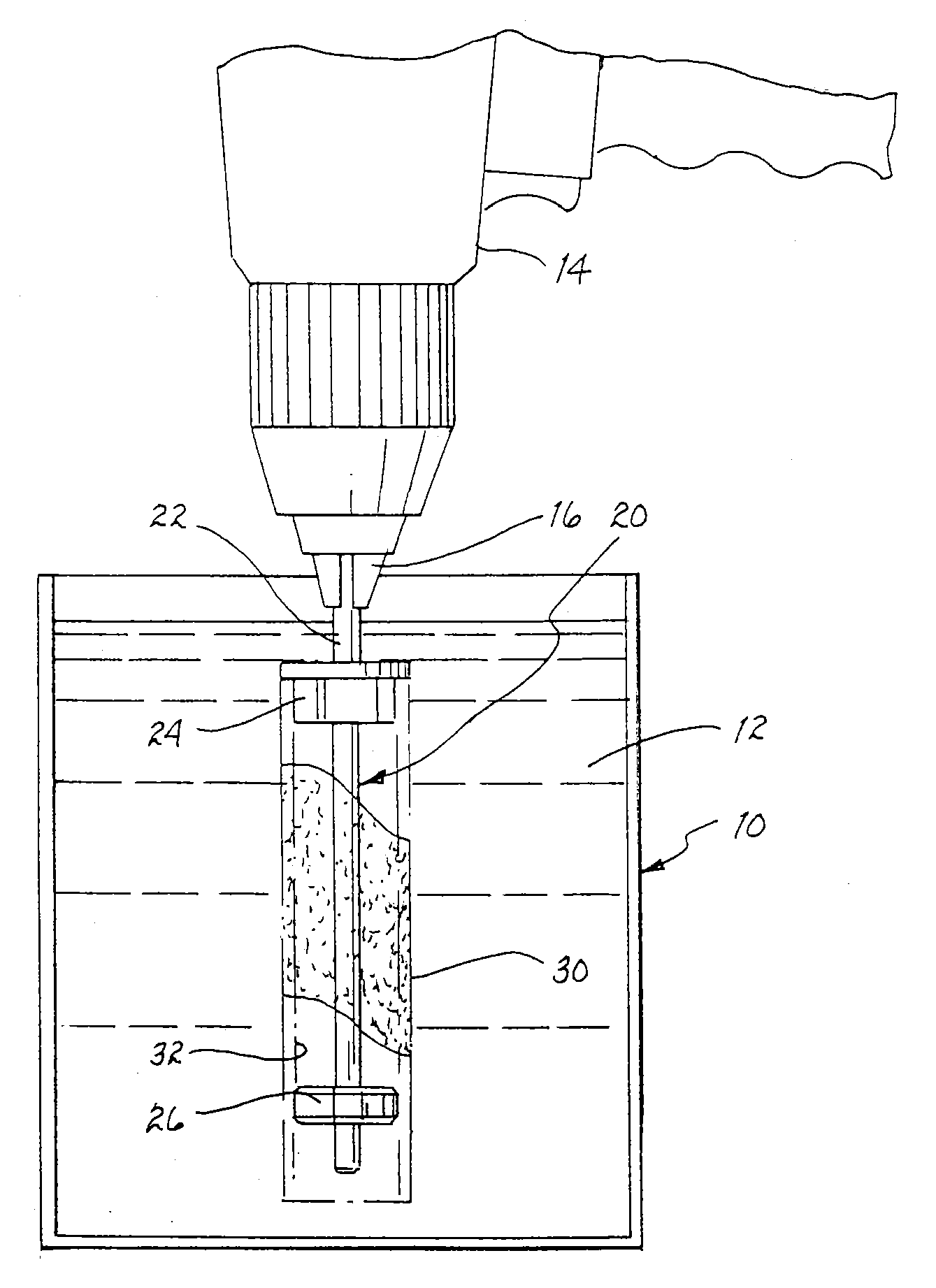
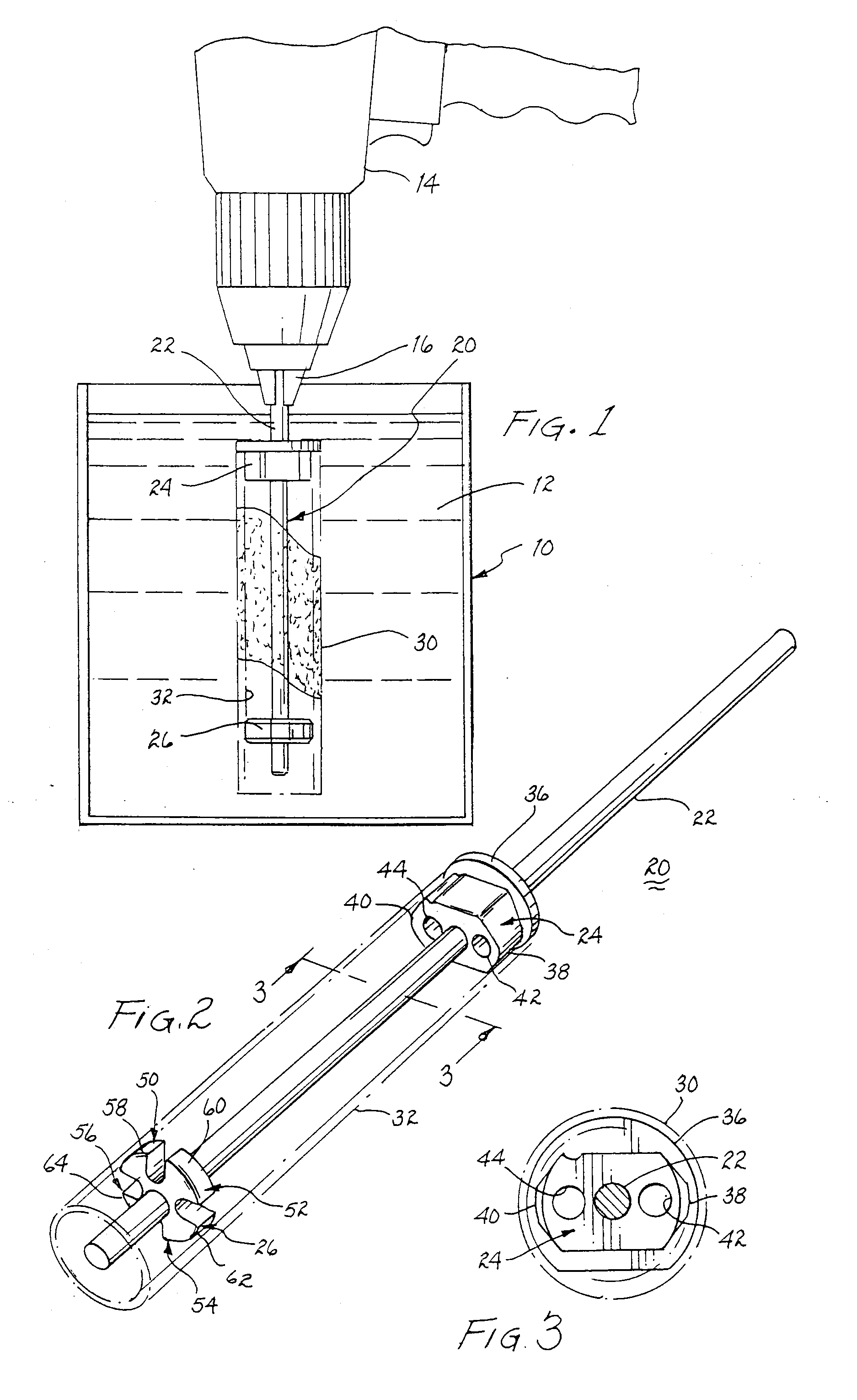
[0041]Referring to FIG. 1, there is illustrated a container 10 having a paint cleaning fluid 12 deposited therein. A conventional manual electric drill 14 includes a conventional chuck 16 for griping and releasing a shaft. A frame 20 includes a shaft 22 for griping engagement with chuck 16, as illustrated. A first support 24 and a second support 26 are fixedly mounted to shaft 22. These two supports provide a mounting for the cylindrical base of a conventional paint roller 30.

[0042]In operation, frame 20 is fixed within chuck 16 before or after paint roller 30 is mounted on the frame. Upon insertion of the frame and mounted paint roller within fluid 12, the fluid will permeate the nap of the paint roller to enhance separation of any paint clinging to the nap or the underlying roller. Upon activating drill 14, frame 20 will spin and impart a commensurate spinning rotation to paint roller 30. The resulting centrifugal force acting upon any residual paint in the nap or on the roller of...


PUM


Abstract

A frame for supporting a paint roller during a cleaning function includes a first support for preventing migration of the paint roller in an axial direction, which first support is fixedly mounted on a shaft engagable with a chuck of an electric drill or crank to impart rotation to the frame and a second support axially displaced from the first support to serve as a mounting supporting an interior surface of the paint roller.

Description

BACKGROUND OF THE INVENTION[0001]1. Field of the Invention[0002]The present invention relates to apparatus for cleaning paint roller, and more particularly, to a frame for supporting a paint roller during immersion and rotation within a cleaning fluid.[0003]2. Description of Related Prior Art[0004]Paint rollers, rotatably supported upon a shaft, have been used for decades to apply paint to essentially flat surfaces in preference to the use of brushes. These paint rollers include a nap of synthetic material of varying thickness depending upon the viscosity of the paint and the smoothness of the surface to be painted. After use, the paint will dry or cure on the roller and render the roller useless.[0005]To save the costs and inconvenience attendant purchasing replacement rollers, various efforts have been undertaken to clean the rollers of the paint residing on and within the nap. In most cases, manual cleaning is time consuming, inefficient and almost never one hundred percent effec...

Claims


Application Information

Patent Timeline
IPC IPC(8): B08B3/10B08B13/00
CPCB44D3/006
Inventor WIKMAN, PETER E.
Owner WIKMAN PETER E
Why Eureka
Try Eureka