Seal ring structure for integrated circuits

Active Publication Date: 2009-12-03
MEDIATEK INC
View PDF32 Cites 26 Cited by
  • Summary
  • Abstract
  • Description
  • Claims
  • Application Information

AI Technical Summary

Benefits of technology

[0008]It is one object of the present invention to provide an improved seal ring structure of an int

Problems solved by technology

However, a major technical hurdle to implementing mixed-signal circuits has been the coupling of noise between different portions of the IC, for example, from the digital to the analog portions.
It has been found that the noise, such as digit

Method used


Image

  • Seal ring structure for integrated circuits
  • Seal ring structure for integrated circuits
  • Seal ring structure for integrated circuits

Examples


Embodiment Construction

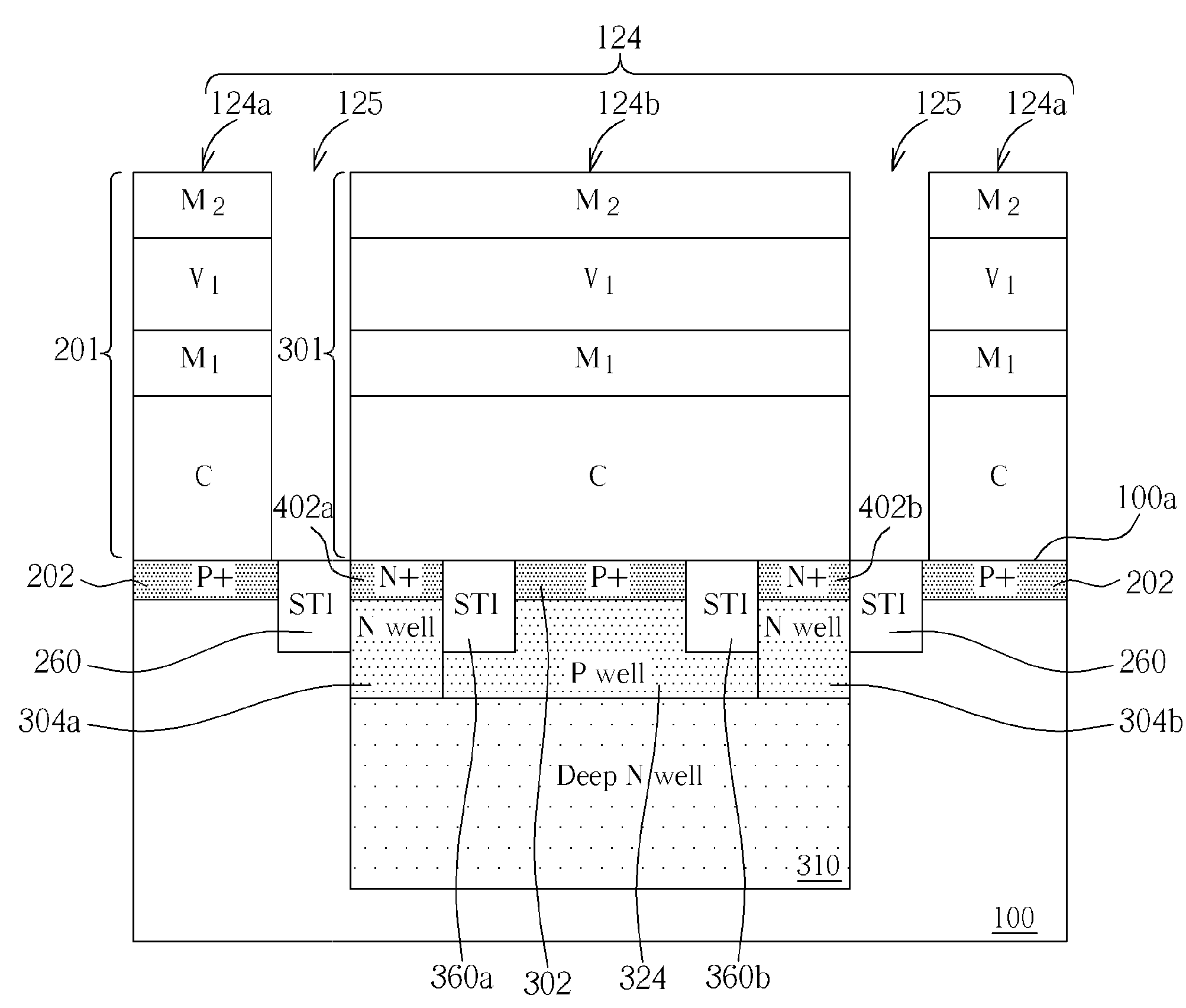
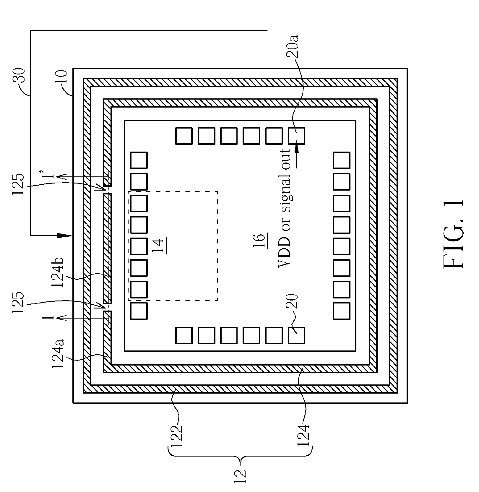
[0019]The present invention pertains to a seal ring structure for an integrated circuit chip. The number of seal ring(s) in the seal ring structure depends on requirements and is not limited to what is illustrated in the embodiments. If there is an outer seal ring, it may be a continuous ring, while an inner seal ring may be divided into at least two portions including a conductive rampart that is situated in front of a sensitive analog and / or RF circuit block of the integrated circuit chip.

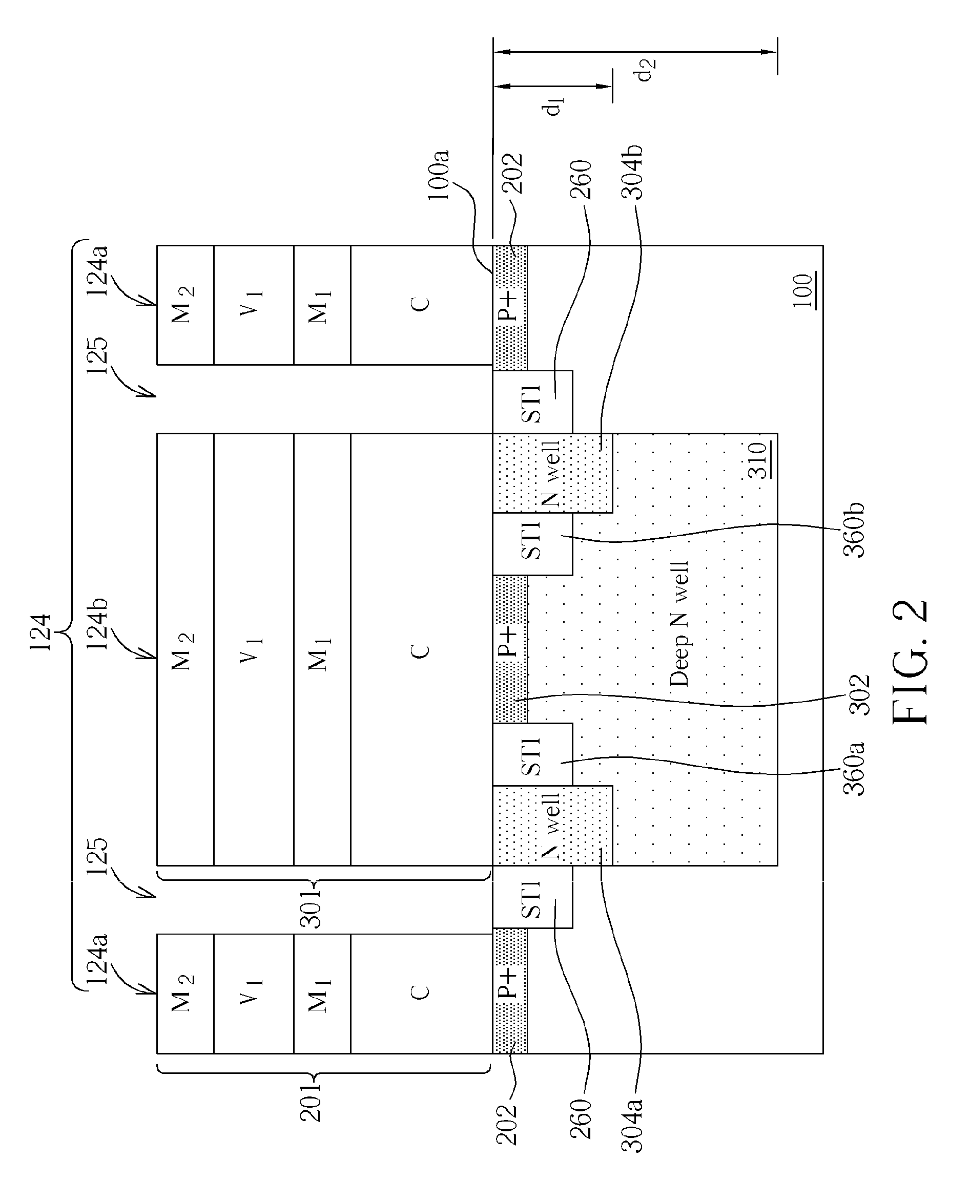
[0020]A deep N well under the conductive rampart may shield the analog and / or RF circuit from noise, which, for example, propagates through the outer seal ring, thereby reducing the noise-coupling effects. The continuous outer seal ring keeps the moisture and corrosive substances from entering the IC.

[0021]Please refer to FIG. 1 and FIG. 2. FIG. 1 is a schematic, planar view of an integrated circuit chip 10 with a double seal ring structure 12 in accordance with one embodiment of this invention. ...


PUM


Abstract

A seal ring structure disposed along a periphery of an integrated circuit. The seal ring is divided into at least a first portion and a second portion. The second portion is positioned facing and shielding an analog and/or RF circuit block from a noise. A deep N well is disposed in a P substrate and is positioned under the second portion. The deep N well reduces the substrate noise coupling.

Description

CROSS REFERENCE TO RELATED APPLICATIONS[0001]This application claims the benefit of U.S. provisional application No. 61 / 057,185, filed May 29, 2008.BACKGROUND OF THE INVENTION[0002]1. Field of the Invention[0003]The present invention related to semiconductor devices and, more particularly, to a seal ring structure for an integrated circuit that is capable of reducing substrate noise coupling.[0004]2. Description of the Prior Art[0005]Advances in fabrication technology have enabled entire functional blocks, which previously had been implemented as plural chips on a circuit board, to be integrated onto a single IC. One particularly significant development is mixed-signal circuits, which combine analog circuitry and digital logic circuitry onto a single IC.[0006]However, a major technical hurdle to implementing mixed-signal circuits has been the coupling of noise between different portions of the IC, for example, from the digital to the analog portions. Ordinarily, an integrated circui...

Claims


Application Information

Patent Timeline
IPC IPC(8): H01L23/552
CPCH01L23/5225H01L23/552H01L23/585H01L2924/0002H01L2924/00
Inventor LEE, TUNG-HSINGCHANG, TIEN-CHANGCHUNG, YUAN-HUNG
Owner MEDIATEK INC
Why Eureka
Try Eureka