Ear Hook Microphone

a microphone and ear hook technology, applied in the field of microphones, can solve the problems of inability to provide more different positions of the microphone to a user, and easy wear and tear so as to prolong the use period of the product, convenient adjustment of the position of the cable pole, and long adjustment distance

Inactive Publication Date: 2009-12-03
WU YING JUI
View PDF1 Cites 4 Cited by
  • Summary
  • Abstract
  • Description
  • Claims
  • Application Information

AI Technical Summary

Benefits of technology

[0007]The ear hook microphone in accordance with the present invention has many advantages than prior arts. After fixing the cable pole adjusting device into the cable pole receiving device, the two parts are fixed in the ear hook. The flexible members can force the pressing block and the button to tightly press the cable pole in order to clip the cable pole stably. We only need to pull the cable pole with pressing on the button to adjust the position of the cable pole. Apparently, the ear hook microphone can conveniently adjust the positions of the cable pole and the microphone, and the adjusting distance is very long, and the usage period of the product is extended because of avoiding bending the cable pole frequently

Problems solved by technology

However, there are still some defects existed in the technology at present.
So we cannot provide more different positions of the microphone to a user.
Even if the user bends the cable pole to adjust the position of the microphone, the cable pole is easy to be worn out or broken after repeated bending.

Method used


Image

  • Ear Hook Microphone
  • Ear Hook Microphone
  • Ear Hook Microphone

Examples


Embodiment Construction

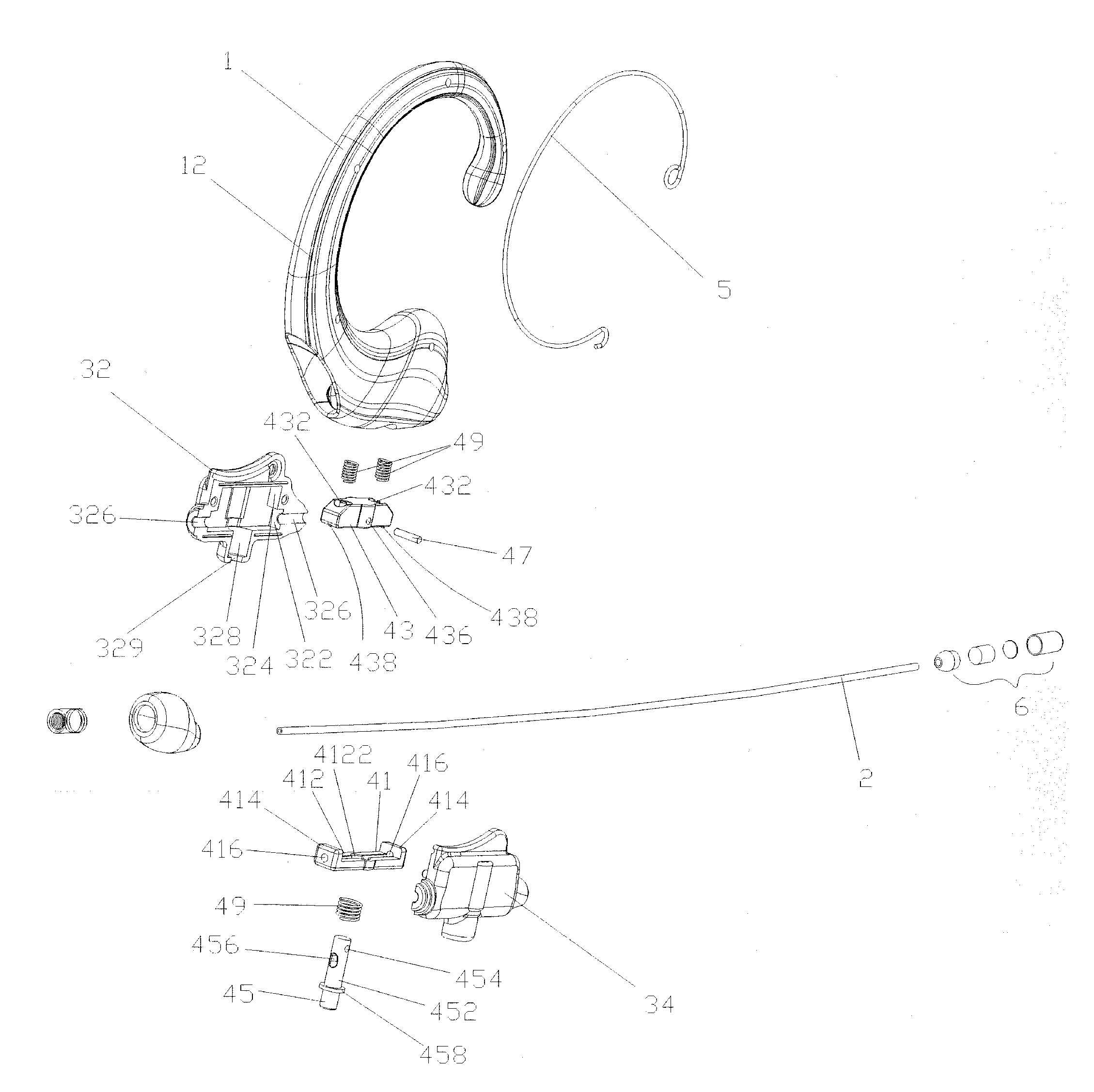
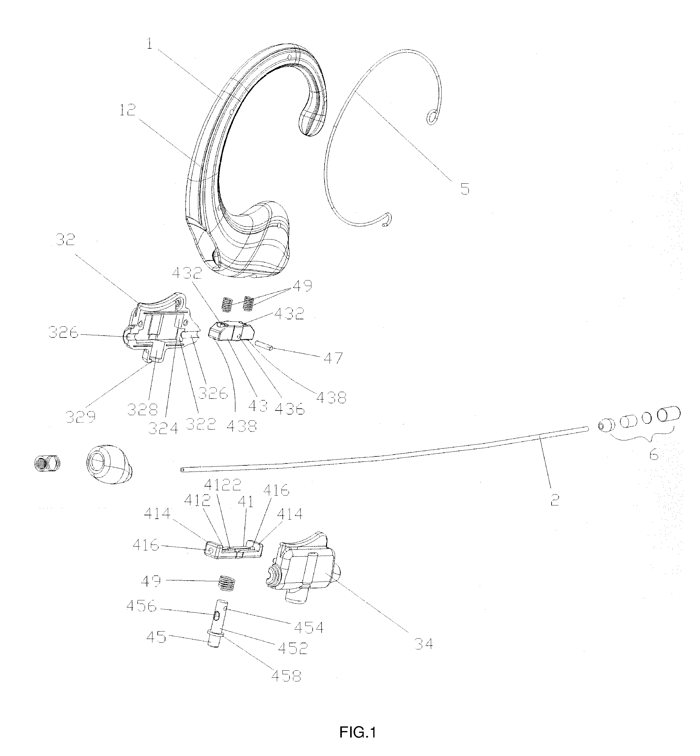
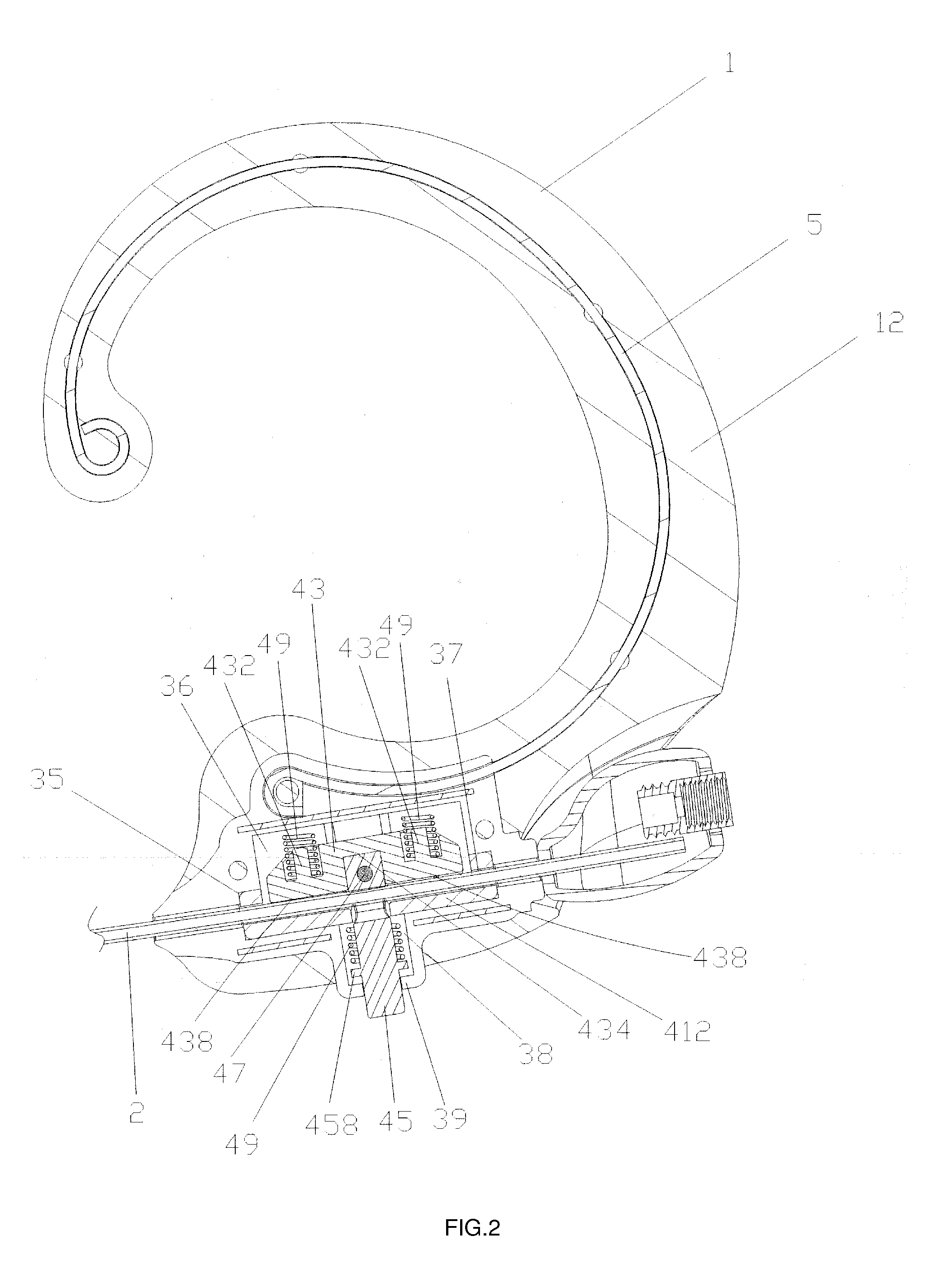
[0010]As shown in FIG. 1 and FIG. 2, an ear hook microphone in accordance with the present invention comprises an ear hook 1, a cable pole 2, a cable pole receiving device (not marked in drawings), a cable pole adjusting device (not marked in drawings), a flexible steel wire 5 and a microphone 6.

[0011]The ear hook 1 is injected with an unclosed semi-surrounding structure, which can be worn on the user's ear. The ear hook 1 includes an injection position 12.

[0012]The cable pole 2 is made of flexible material, which can be bended. A plurality of cables (not shown in drawings) which be used to transmit electric signals are defined inside of the cable pole 2.

[0013]The cable pole receiving device is fixed in the injection position 12 of the ear hook 1. The cable pole receiving device comprises a first receiving component 32 and a second receiving component 34.

[0014]The first receiving component 32 and the second receiving component 34 can be put together to become an integrated whole by ...


PUM


Abstract

An ear hook microphone comprises an ear hook, a cable pole, a cable pole receiving device and a cable pole adjusting device. The ear hook comprises an injection position. The cable pole receiving device is fixed in the injection position and comprises an underlying flange. The cable pole adjusting device is fixed in the cable pole receiving device, which includes a fixed block, a pressing block, a button and a plurality of flexible members. The fixed block includes a base plate. A button hole is formed in the middle of the base plate. Two side plates upwardly extend from the two opposite ends of the base plate respectively. Each of the two side plates opens a through hole at the cable pole. The pressing block is placed between the two side plates. The top end of the button inserts through the button hole then connects with the pressing block. The button comprises a bar. The top end of the bar has a perforated hole. An upborne flange protrudes from the lower portion of the bar. The upborne flange shall be placed on the underlying flange. The plurality of flexible members are fixed to press the cable pole tightly. The cable pole is inserted into the two through holes and the perforated hole.

Description

BACKGROUND OF THE INVENTION[0001]The present invention relates to a kind of microphone.[0002]With progress of technology and improvements of people's living conditions, various high-tech products are widely used more and more. For example, all kinds of microphones are used in a meeting room or other business occasions. We have designed a lot of different microphones including ear hook microphones.[0003]For the ear hook microphone presently, an ear hook microphone usually includes an ear hook which is worn on a user's ear, a cable pole which extends forwardly from the ear hook and a microphone which is connected at the distal end of the cable pole. The product is made of common metallic tube, to some extent, it is flexible and is helpful for restoring the original shape after using. The Chinese utility model patent NO.: 200520011973.1 with the title “An Ear Hook Microphone” filed on Apr. 30, 2005. has many progress on the basis of the prior art. The ear hook microphone includes an ea...

Claims


Application Information

Patent Timeline
Patent Type & Authority Applications(United States)
IPC IPC(8): H04R23/00
CPCH04R1/083H04R1/06
Inventor WU, YING JUI
Owner WU YING JUI
Why Eureka
Try Eureka