Line Spring Jack and Its Assembly Method

a technology of spring jack and assembly method, which is applied in the manufacture of contact member parts, coupling contact parts, coupling device connections, etc., can solve the problems of more difficulty in assembly of positioning plugs into grooves, required hole enlargement equipment and processes,

Active Publication Date: 2009-12-03
BYD CO LTD
View PDF8 Cites 21 Cited by
  • Summary
  • Abstract
  • Description
  • Claims
  • Application Information

AI Technical Summary

Benefits of technology

[0011]According to an embodiment of the invention, a method of assembling a line spring jack is disclosed. The method comprises the steps of: providing a jack body, a jack cap, one or more ling spring wires, and a positioning plug, in which the jack body comprises an open end and a close end and a plug hole therein between the open end and the close end, the plug hole further including a groove near the close end of the jack body, the caliber of the groove may be smaller than the caliber of the rest of the plug hole; and the jack cap may further include a through hole via which the plug hole is exposed externally; placing the one or more line spring wires in the plug hole of the jack body; placing a first portion of the positioning plug within the groove and a second potion of the positioning plug within the rest of the plug hole; fixing the jack cap to the jack body near the open end such that a first end of the one or more line spring wires is located within a space between an interior surface of the jack cap and an exterior surface of the jack body; and placing a second end of the one or more line spring wires between an exterior surface of the second portion of the positioning plug located within the plug hole and an interior surface of the jack body.

Problems solved by technology

Therefore, the hole enlarging equipment and process are required.
Meanwhile, the assembly of putting the positioning plug into the groove may be more difficulty.

Method used


Image

  • Line Spring Jack and Its Assembly Method
  • Line Spring Jack and Its Assembly Method
  • Line Spring Jack and Its Assembly Method

Examples


Embodiment Construction

[0024]The aforementioned features and advantages of the invention as well as additional features and advantages thereof will be more clearly understood hereinafter as a result of a detailed description of the following embodiments when taken in conjunction with the drawings.

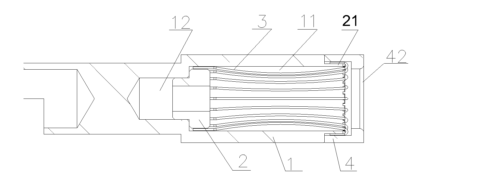
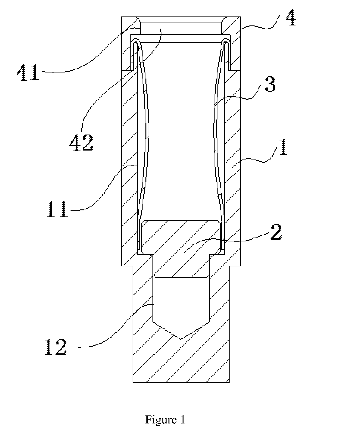
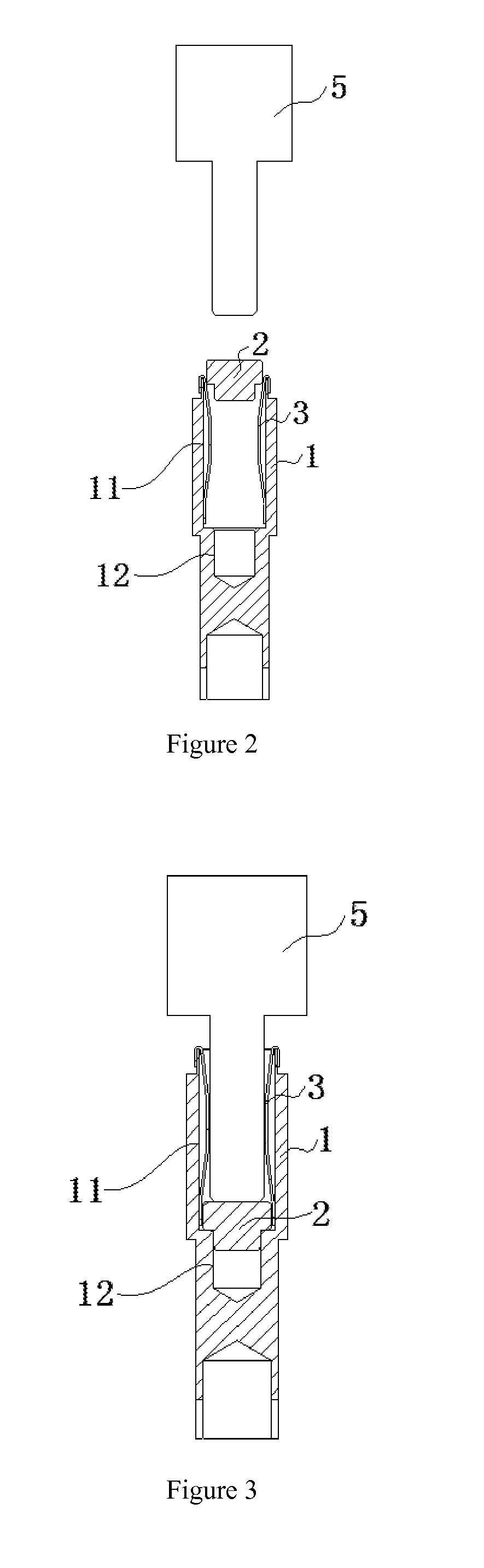
[0025]As shown in FIG. 1, one embodiment of the present invention provides a line spring jack. The line spring jack comprising: a jack body 1, a jack cap 4, one or more line spring wire 3 and a positioning plug 2; said jack body 1 further comprises an open end, a close end and a plug hole 11 therein between the open end and the close end; said line spring wire 3 is located in the plug hole 11 of said jack body 1; said jack cap 4 is tightly connected to one end of the jack body 1; said jack cap 4 further comprises a through hole 42 which is communicated with said plug hole 11; one end of the line spring wire 3 may be located within a space defined between an interior surface of the jack cap 4 and an exterior surfa...


PUM

PropertyMeasurementUnit
external diameteraaaaaaaaaa
distanceaaaaaaaaaa
diameteraaaaaaaaaa

Abstract

A line spring jack and an assembling method are disclosed. The line spring jack comprises a jack body, a jack cap, a line spring wire and a positioning plug. Said jack body further comprises a plug hole; said line spring wire is located in said plug hole; said jack cap is connected to one end of said jack body; said jack cap further comprises a through hole connected to said plug hole; one end of line spring wire is clipped in a space formed between said jack cap and said jack body; wherein said plug hole further comprises a groove in the bottom; the caliber of the groove is smaller than the caliber of said plug hole; said positioning plug includes a part in the groove and a part in the plug hole, the part in the groove is tightly matched to said groove.

Description

CROSS-REFERENCE TO RELATED APPLICATION[0001]This application claims priority to and benefit of Chinese Patent Application Serial No. 200810108661.0, filed in the State Intellectual Property Office of the P. R. China on May 30, 2008, and the Chinese Patent Application Serial 200910105668.1, filed in the State Intellectual Property Office of the P. R. China on Feb. 27, 2009, the entire contents of which are incorporated herein by reference.BACKGROUND OF THE INVENTION[0002]1. Field of the Invention[0003]The present invention relates to a line spring jack and an assembly method.[0004]2. Background of the Related Art[0005]A connector is an important device in the field of industrial electrical equipment and charging electric automobile. The key part of a connector is a metal clip terminal. As the key part of current conducting, the requirement of its insertion-withdrawal force, insertion-withdrawal frequencies and contact resistance is very high.[0006]The combination of a line spring jac...

Claims


Application Information

Patent Timeline
Patent Type & Authority Applications(United States)
IPC IPC(8): H01R13/187H01R43/20
CPCH01R13/187H01R13/33Y10T29/49204Y10T29/49183Y10T29/49208H01R43/16
Inventor LI, ZHANYE, YUANNING, CHEN
Owner BYD CO LTD
Why Eureka
Try Eureka