

Method for Predicting the Best and Worst in a Set of Non-Unique Solutions
a non-unique solution and solution technology, applied in the field of geophysical modeling, can solve the problems of time-consuming methods, generally not matching the observed data in a forward modeling sense, and not necessarily the “best” and “worst” case answers
Active Publication Date: 2009-12-03
EXXONMOBIL UPSTREAM RES CO
View PDF70 Cites 4 Cited by
- Summary
- Abstract
- Description
- Claims
- Application Information
AI Technical Summary
Benefits of technology
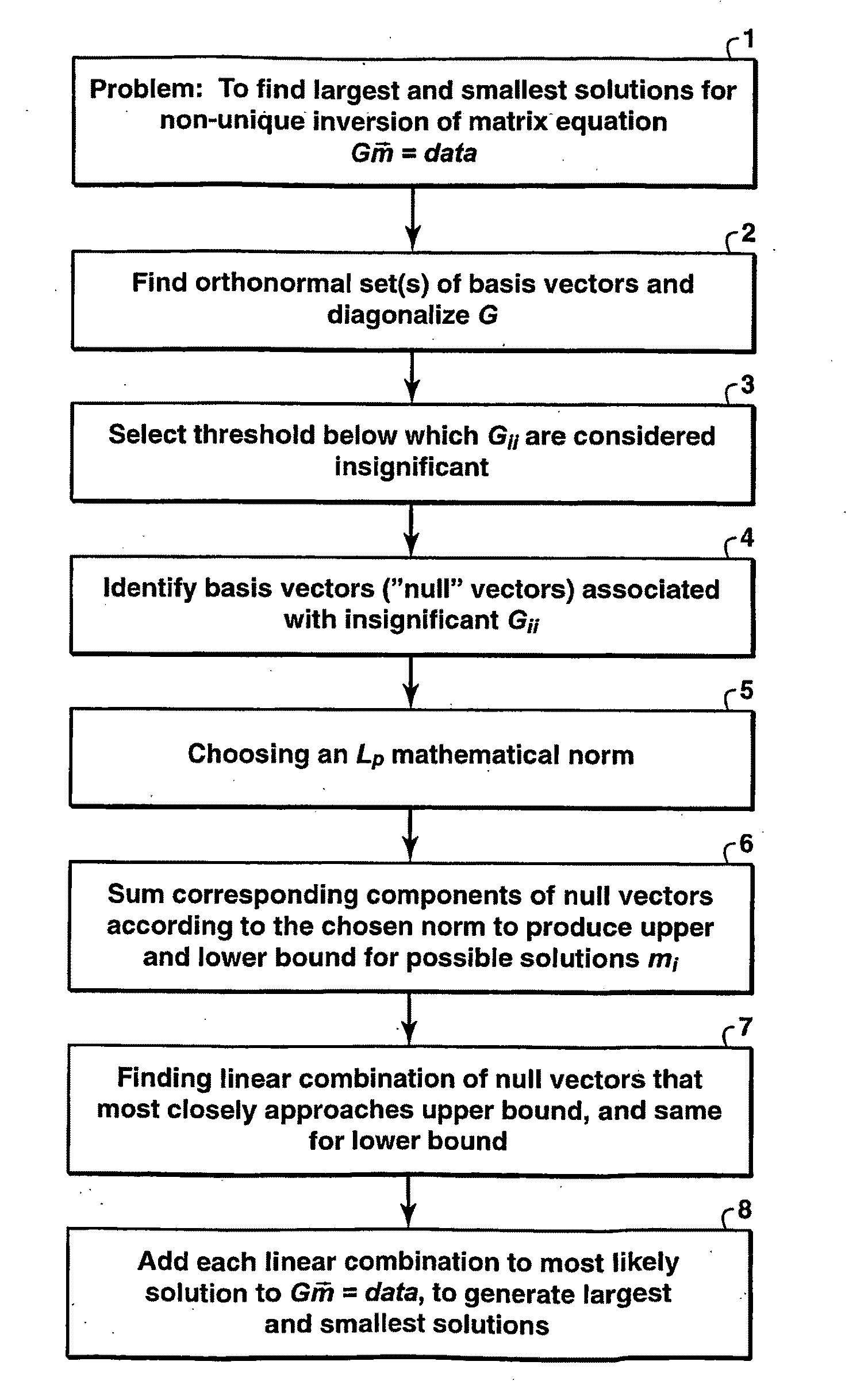
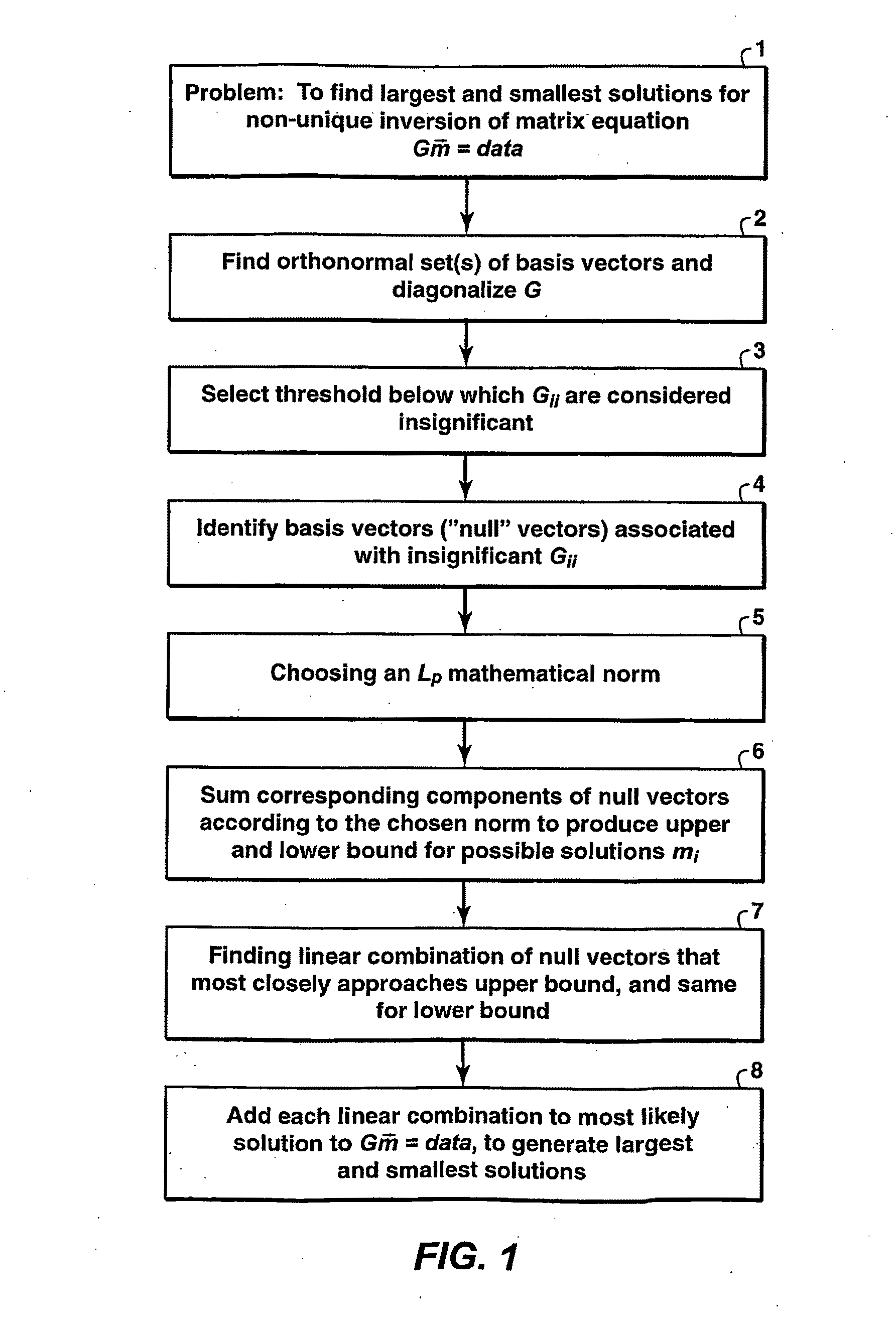
[0007]In one embodiment, the invention is a computer-implemented method for (see box 1 of the flowchart of FIG. 1) determining the largest and smallest of the possible solutions of a matrix equation that can be expressed in the form[G][m1m2⋮mN]=[data],where m1 . . . mN are physical parameters to be solved for and G is a matrix based on a model of a physical system that relates the mi to measured data, wherein the equation may be non-uniquely inverted by numerical methods yielding an infinite number of possible solutions all of which fit the data substantially equally well and from which a most likely solution can be determined, said method comprising (a) finding (step 2 in FIG. 1) orthonormal basis vectors that diagonalize the G matrix, and using said vectors to diagonalize G; (b) selecting (step 3) a threshold below which the values of the elements of the diagonalized G are considered insignificant in terms of their effect on the most likely solution to said matrix equation; (c) identifying (step 4) from the orthonormal basis vectors those vectors (the “null” vectors) associated with the insignificant diagonal elements; (d) choosing (step 5) an Lp mathematical norm where p∈[0, ∞]; (e) determining (step 6) an upper and lower bound for possible solutions m1, m2 . . . mN by summing corresponding components of said null vectors according to the chosen norm, said lower bound being given by the negative of said sums; (f) finding (step 7) a linear combination of the null vectors that most closely approaches said upper bound, and repeating this finding for said lower bound; and (g) adding (step 8) each of said two linear combinations in turn to the most likely solution to yield a largest and a smallest solution, scaling as needed to eliminate any physically unreal results.
Problems solved by technology
This method is time-consuming because it requires a large number of forward models.
In addition, it suffers from user bias in that the only models tried are the ones that the user has thought of or deemed relevant.
This method produces results that generally do not match the observed data in a forward modeling sense and are not necessarily the “best” and “worst” case answers.
Method used
View moreImage
Smart ImageViewing Examples

Examples
example
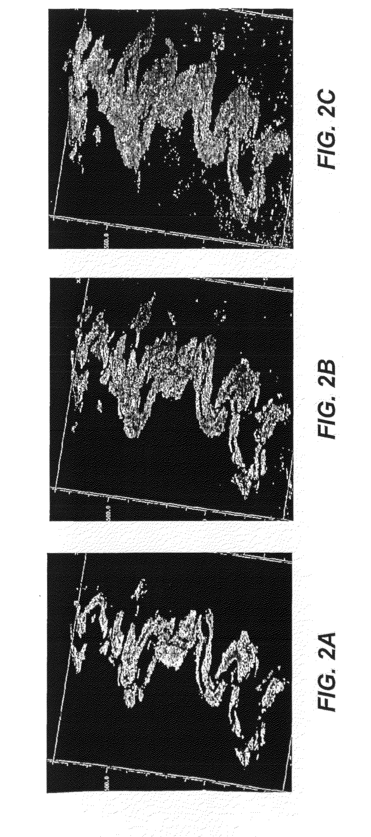
[0021]The present inventive method was applied to some seismic data acquired over a potential oil field. FIGS. 2A-C show a 3-D image on a black background of, respectively, the “worst,”“most-likely,” and “best” inferred (1—vshale) sand channel winding through a inverted vshale volume (the shaly parts have been made invisible). The estimates of total reserves carried in the “best” and “worst” case scenarios varies by almost a factor of two. In addition, the difference in connectedness between the sand bodies in the “worst” and “best” cases are significantly different and imply different draining strategies that might be optimal for this field.
Login to View More PUM
 Abstract
Method for determining best and worst cases for values of model parameters such as porosity and shale volume fraction generated by non-unique matrix inversion of physical data such as seismic reflection amplitudes. The matrix is diagonalized, and then orthonormal basis vectors associated with insignificant diagonal elements are used to generate upper and lower bounds on the solution. Best and worst case solutions are determined as linear combinations of the null basis vectors, where the expansion coefficients are determined by making a best fit to the upper and lower bounds.
Description
[0001]This application claims the benefit of U.S. Provisional Application No. 60 / 698,760 filed on Jul. 13, 2005.FIELD OF THE INVENTION[0002]This invention relates generally to the field of geophysical modeling, although the invention has broader application. Specifically, the invention is a method for predicting best and worst solutions when model inversion yields non-unique solutions.BACKGROUND OF THE INVENTION[0003]In the oil industry, it is common to be faced with a set of data from which one wishes to infer some sort of information of interest. It is also fairly common that such inverse problems are non-unique, that is, different solutions explain the data equally well. While it is straightforward to obtain a single solution that the user considers “most likely”, it is often desirable to know the “best” and “worst” case solutions that fit the data in addition to the “most likely” one, to adequately understand the risks of a given course of action. An example of this sort of prob...
Claims
Login to View More Application Information
Patent Timeline
 IPC IPC(8): G06F17/10G01V1/00G06F19/00
CPCG01V1/306
InventorSALTZER, REBECCA L.FINN, CHRISTOPHERKEYS, ROBERT
OwnerEXXONMOBIL UPSTREAM RES CO