

Personal protection apparatus for vehicles
a technology for personal protection and vehicles, applied in the direction of shields, protective equipment, armoured vehicles, etc., can solve the problems of increased fuel consumption, increased vehicle weight, and high cost of such vehicles
- Summary
- Abstract
- Description
- Claims
- Application Information
AI Technical Summary
Benefits of technology
Problems solved by technology
Method used
Image

Examples
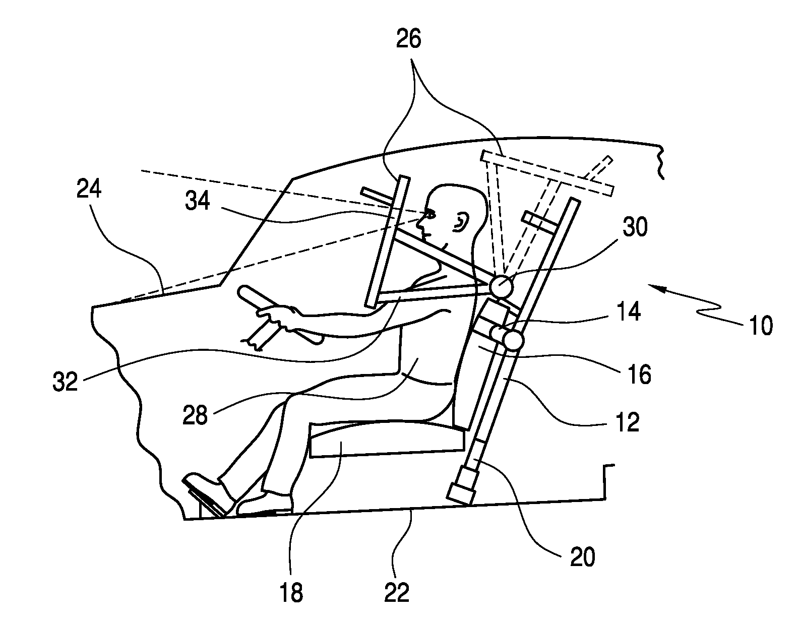
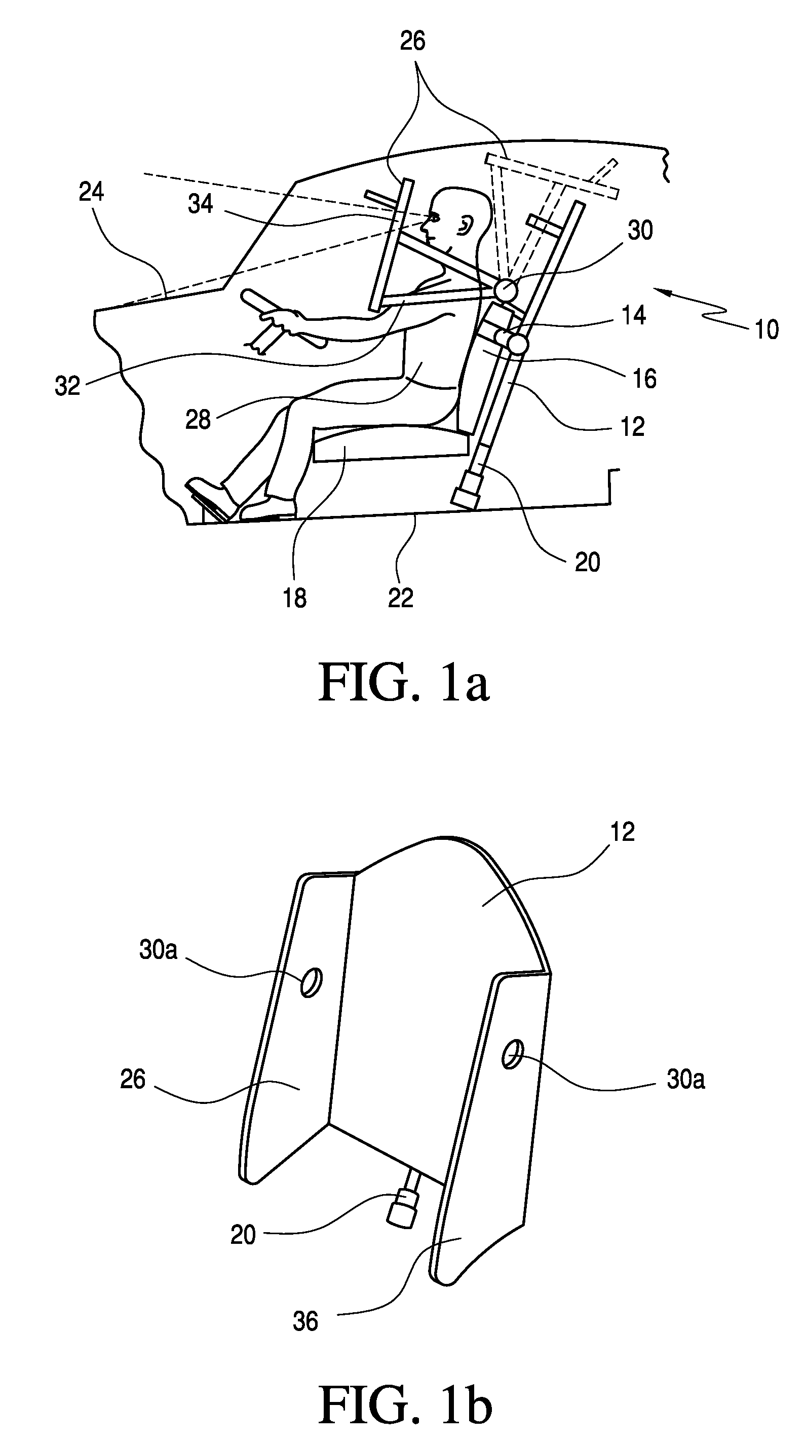
embodiment 10
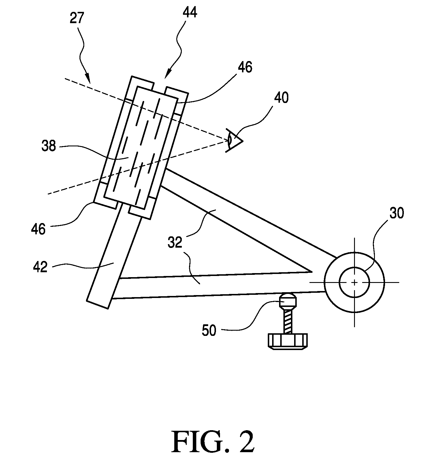
[0057]Referring now to FIG. 2, there is seen a further embodiment of a visor 27. A transparent sector 38 is disposed in an area proximate to the eyes 40 of a driver. The visor 27 provides a wider field of view than is available in the embodiment 10 seen in FIG. 1. In the present figure there is seen a lower part 42 made of steel, an upper part 44 made of a transparent material (armored glass or polycarbonate) held in a frame 46 attached to the lower part. The frame in an optional item, as the lower and upper parts could overlap and be directly attached to each other.
[0058]Again as in FIGS. 1a and 1b, visor 27 is linked to the behind-the-seat ballistic shield 12, seen in FIGS. 1a and 1b, by a hinge arrangement 30, struts 32 being provided at each side to support and position the visor 27.
[0059]An adjustable stop unit 50 is provided to suit drivers of varying height.
third embodiment
[0060]FIG. 3 illustrates a visor 48 made entirely of polycarbonate. The visor 48 is lighter but thicker than the steel visor 26 described with reference to FIG. 1a. The visor 48 is easily molded or hot-bent to its desired shape, providing manufacturing advantages.
[0061]The visor comprises of a front face 52 curved in two dimensions. Depending side walls 54, 56 support two apertures 30a which are a part of the hinge arrangement 30 of the visor. The slots 58 are part of an arrangement for optional fastening the visor to side protection panels 36 seen in FIG. 1b.
[0062]Seen in FIG. 4 is further embodiment of the mechanism related to the visor 60 in the protection apparatus 62 for use in vehicles. In the present embodiment the visor 60 is linked to the behind-the-seat ballistic shield (12 seen in FIG. 1) by an articulated track 64.
[0063]The visor storage position is substantially above and slightly behind the head of the driver 28. This position, seen in FIG. 1a, thus provides some addi...
embodiment 70
[0065]Turning now to FIG. 5, there is seen in the figure an embodiment 70 provided with an articulated track 68 which is longer than the track 64 seen in FIG. 4. The track 68 allows storage of the visor 60 at the rear of the behind-the-seat ballistic shield 12 and thus allows the driver 28 an unobstructed rear view.
[0066]With reference now to FIG. 6, there is seen a visor 48, as shown and described in FIG. 3, hinged to and supported by a behind-the-seat ballistic shield 70 integrally molded to with side protection panels 72. The visor 48 fits into the space between the two panels 72.
[0067]Both the visor 48 and the behind-the-seat ballistic shield 70 are made of a transparent grade of polycarbonate, offering the driver a maximum field of view.
PUM
 Abstract
Description
Claims
Application Information