Side handle luggage

a technology of side handles and luggage, applied in the field of luggage and handles, can solve the problems of providing the frustration of luggage users, affecting the use of luggage, and causing great frustration, and achieve the effect of facilitating the movement of extension members

Inactive Publication Date: 2009-12-10
HYMAS AMMON BRUCE
View PDF11 Cites 23 Cited by
  • Summary
  • Abstract
  • Description
  • Claims
  • Application Information

AI Technical Summary

Benefits of technology

[0023]The grip can facilitate movement of the extension members. For instance, the grip may have pockets formed therein that align with the extension members. The pockets are sized to not only receive the extension members, but also to permit the extension members to move laterally within the pocket, and so that the angle of the grip can change by at least ten degrees. The handle assembly may also include advertising indicia on the extension members, grip, or other portions thereof.

Problems solved by technology

Often, such trips are for extended periods and require the user to pack additional clothing, toiletries, and other items to be used during that stay.
Such luggage is the source of great frustration as the luggage can be difficult to pack, carry, and move.
Such design has, however, provided its own source of frustration for luggage users.
Existing handles for luggage, however, do not conform to such natural movement.
However, by angling the arm backward, the user's arm is in an unnatural and awkward position.
This can also cause the user to strain to walk in a straight line, or to cause the luggage to follow in a straight line.
With the luggage itself, the one or two bars both take up space within the luggage, and also create an uneven surface that causes the user to strategically place his clothes around the bars.
Clothes may thus get wrinkled and users can get frustrated by having to pack around the bars.

Method used


Image

  • Side handle luggage
  • Side handle luggage
  • Side handle luggage

Examples


Embodiment Construction

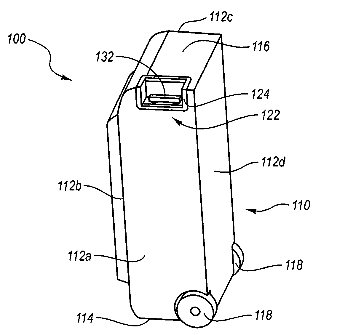
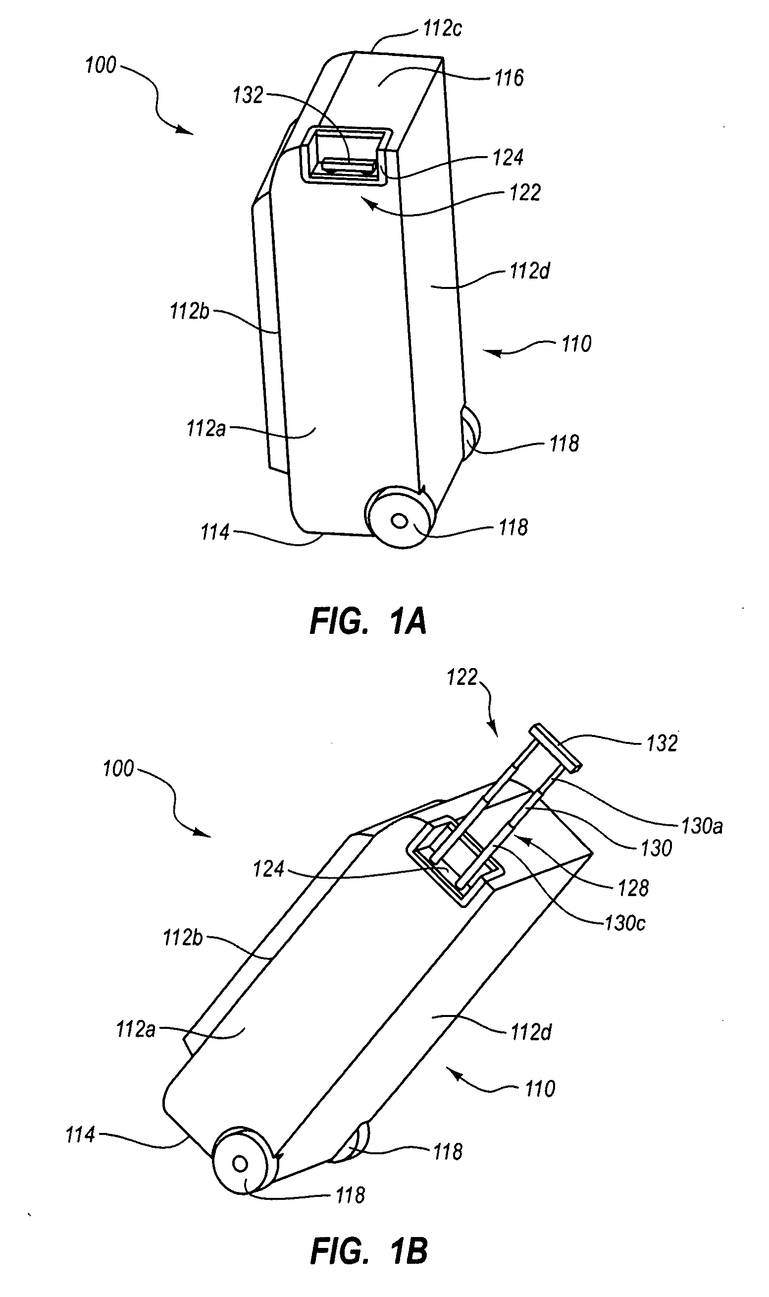
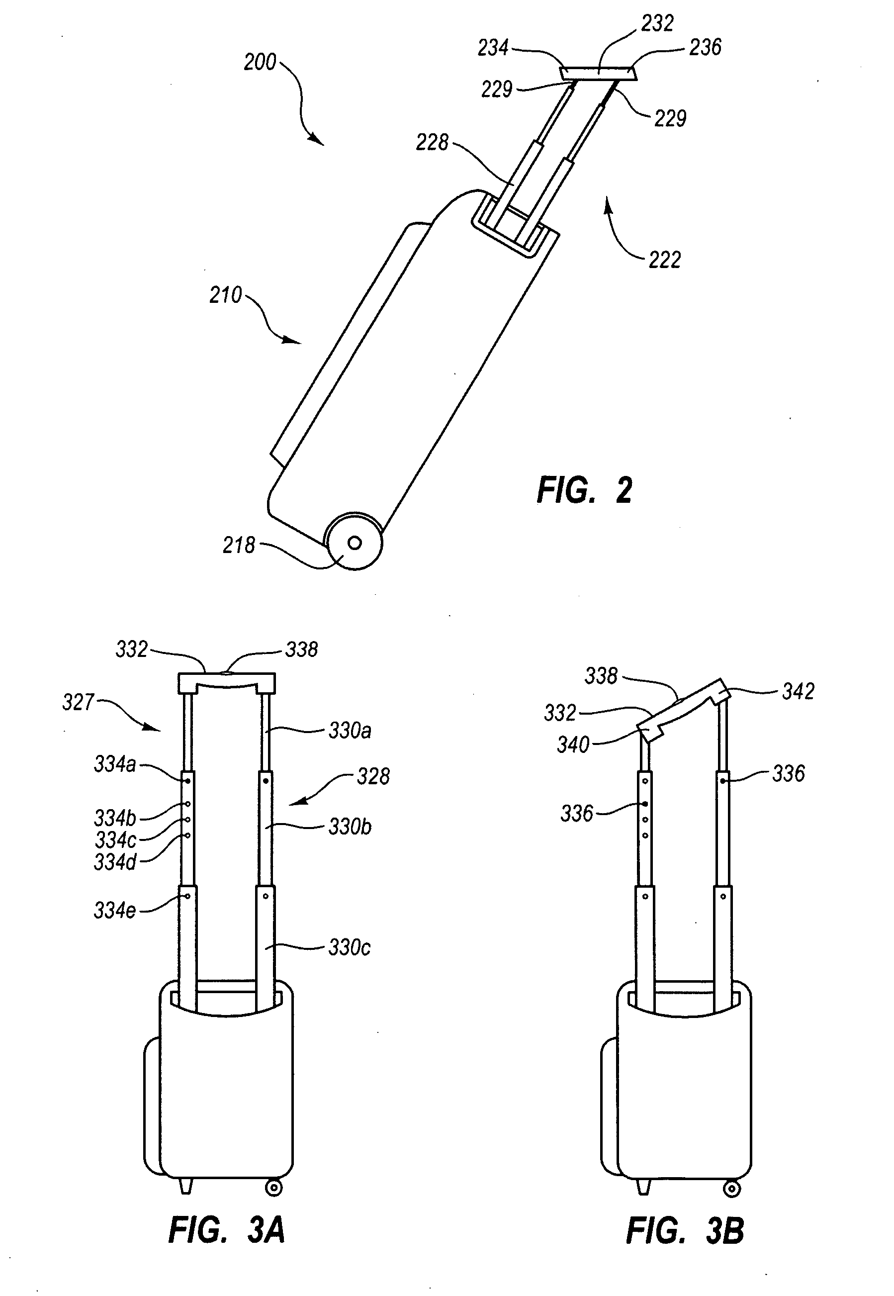
[0013]In general, embodiments described in this application relate to luggage and handles for handling and transporting the same. For instance, exemplary embodiments relate to a handle that is placed on the side of an article of luggage to allow the luggage handle to be positioned at the side of the user, while the user then totes the luggage directly behind him. In other embodiments, the luggage may additionally, or alternatively, have a handle that pivots or is inclined so that when a user tilts an article of luggage, the handle can allow the user to walk with the user's hand in a more natural position.

[0014]According to one aspect of the invention, a suitcase is described and includes a container for storing items, and wheels attached to the bottom of the container. A handle is also provided. In contrast to conventional handles which extend from the center of the back surface of such a container / suitcase and parallel thereto, the invention includes a handle which extends from the...


PUM


Abstract

An article of luggage is described and includes a container with wheels attached thereto. A handle is also provided. In contrast to conventional handles which extend from the center of the back surface of a piece of luggage, and parallel thereto, the described handle extends from the side of the luggage, and is oriented substantially perpendicular to the back surface. This allows, for example, the user to wheel the container behind him / her, while gripping the handle at the user's side, rather than requiring that the user either have the luggage not follow directly behind the user, or place his / her hand behind him to keep the luggage positioned behind the user. The handle may be stored along side or base of the luggage. The handle can include a grip that pivots to allow a user to selectively change the angle of the grip relative to the luggage.

Description

CROSS-REFERENCE TO RELATED APPLICATIONS[0001]This Application claims the benefit of, and priority to, U.S. Patent Application Ser. No. 61 / 042,530, filed on Apr. 4, 2008 and entitled “IMPROVED HANDLE FOR LUGGAGE,” which application is hereby incorporated herein by this reference, in its entirety.BACKGROUND[0002]1. Field of the Invention[0003]The embodiments disclosed herein generally relate to handling systems. More particularly, embodiments of the invention relate to luggage and handles for such luggage.[0004]2. Background of the Invention[0005]In the present, many forms of transportation exist and allow people to travel between locations near and far in only a matter of hours. Often, such trips are for extended periods and require the user to pack additional clothing, toiletries, and other items to be used during that stay. Much of the luggage (e.g, suitcases, travel bags, etc.) that are used for such packing continue to employ designs that have been around for many years—if not de...

Claims


Application Information

Patent Timeline
Patent Type & Authority Applications(United States)
IPC IPC(8): A45C5/14A45C3/00A45C13/30
CPCA45C5/14A45C2013/267A45C2013/265A45C13/262
Inventor HYMAS, AMMON BRUCE
Owner HYMAS AMMON BRUCE
Why Eureka
Try Eureka