
Headrest for a vehicle seat

a headrest and vehicle seat technology, applied in the field of headrests for vehicle seats, can solve the problems of deteriorating locking function, uncomfortable movements, and threatening traffi

Inactive Publication Date: 2009-12-10
KONGSBERG AUTOMOTIVE AS
View PDF12 Cites 50 Cited by
  • Summary
  • Abstract
  • Description
  • Claims
  • Application Information

AI Technical Summary

Benefits of technology

[0004]There is therefore a need for a solution by which a moving wing in a headrest can be manoeuvred in a manner which offers greater traffic safety than hitherto known solutions. Such a solution should expediently also offer improved functionality which is not at risk of being degraded over time.
[0007]Furthermore, the moving part—the wing—is maintained in a desired position by the inflated inflatable element between the wing and a fixed part in the headrest, which eliminates the need for solutions reliant upon friction for the locking function. A locking function is thus created which does not suffer from wear in the same way as a friction solution.

Problems solved by technology

A drawback with currently known solutions as regards moving wings in headrests is that they have to be adjusted by hand, which can endanger traffic and lead to uncomfortable movements.
A further drawback with currently known solutions is that the wings are locked in a set angular position by means of friction, mechanical engagements or the like, which leads to wear, and thus to deteriorated locking function after a period of use.

Method used


Image

  • Headrest for a vehicle seat
  • Headrest for a vehicle seat
  • Headrest for a vehicle seat

Examples


Embodiment Construction

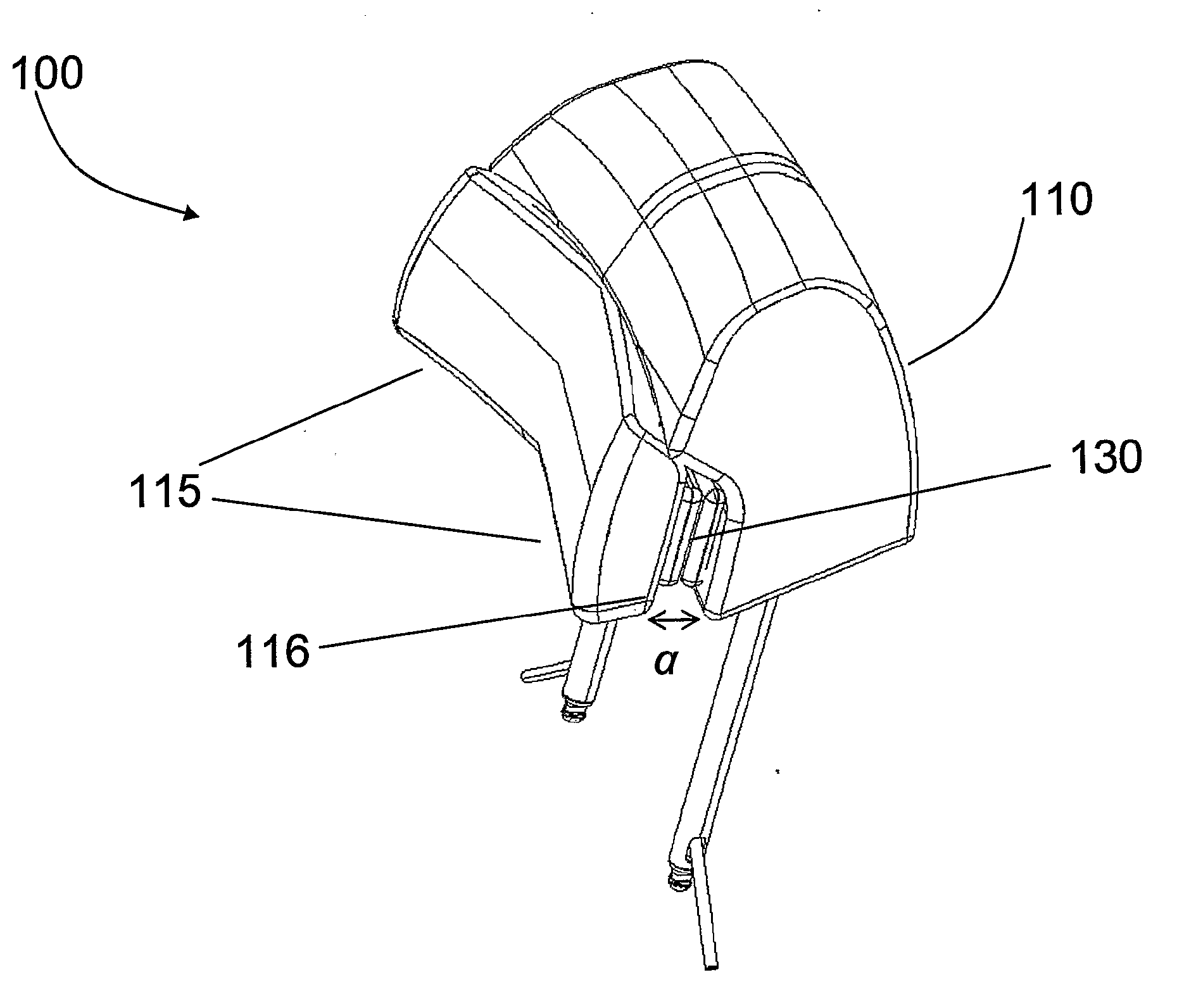
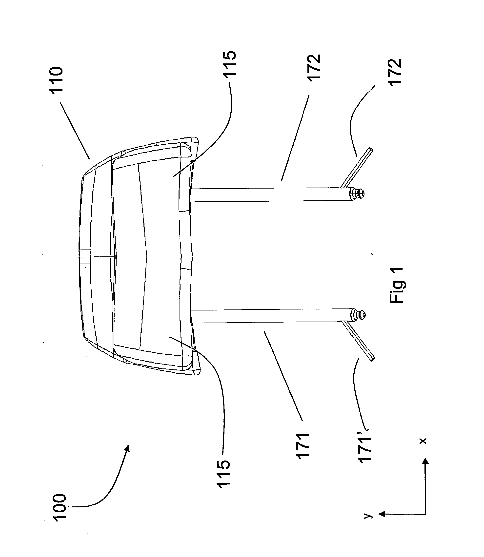
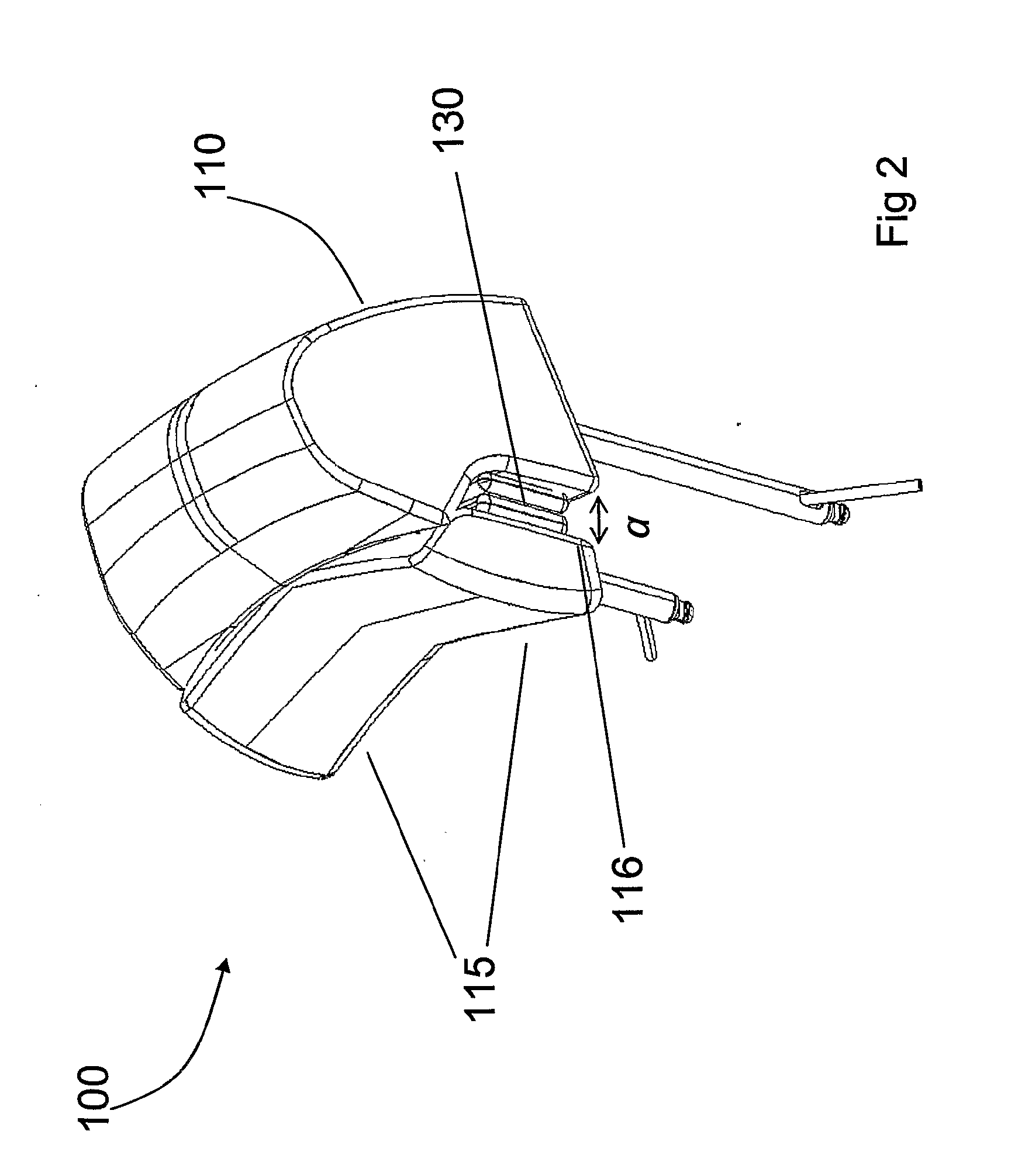
[0016]In FIG. 1, a headrest 100 according to the invention is shown. As can be seen, and as will be described in greater detail further below, the headrest 100 comprises a fixed part 110 for attachment in a vehicle seat, and at least a first moving part 115. Furthermore, the headrest can comprise, or be connected to, a first 171 and a second leg 172.

[0017]In FIG. 1 and throughout the description, the headrest is shown to comprise two moving parts 115, symmetrically arranged in the headrest 100, which is a preferred embodiment. It will be appreciated, however, that the number of moving parts, as well as their positioning in the headrest, can in principle be freely varied within the scope of the invention.

[0018]The moving part 115 is disposed in a mounting (not shown in FIG. 1) in the fixed part 110 in such a way that the moving part 115 can be moved forward and back relative to the back of the head of the person who is to sit in the seat, and can thus offer at least a first and a sec...


PUM


Abstract

The invention relates to a headrest (100) for a vehicle seat, comprising a fixed part (110) for attachment in a vehicle seat and at least a first moving part (115), which moving part (115) is movably mounted in amounting (120) in the fixed part so that it can be moved between a first and a second position relative to the fixed part (110). The movement of the moving part (115) from the said first position to the said second position is achieved by means of an inflatable element (130) in the headrest (100), which is inflated by compressed air and thus expands, and the first moving part (115) is maintained in the said second position by means of the inflated inflatable element (130).

Description

TECHNICAL FIELD[0001]The invention relates to a headrest for a vehicle seat, comprising a fixed part for attachment in a vehicle seat, and at least a first moving part. The first moving part is movably mounted in a mounting in the fixed part, so that it can be moved between a first and a second position relative to the fixed part.BACKGROUND ART[0002]Headrests for vehicle seats are well known, and often comprise moving parts, so called “wings”, which are movably secured in the headrest, and the angular position of which relative to the headrest can be adjusted according to requirement and can thus provide support for the head in the lateral direction.[0003]A drawback with currently known solutions as regards moving wings in headrests is that they have to be adjusted by hand, which can endanger traffic and lead to uncomfortable movements. A further drawback with currently known solutions is that the wings are locked in a set angular position by means of friction, mechanical engagement...

Claims


Application Information

Patent Timeline
IPC IPC(8): B60N2/48
CPCB60N2/4882B60N2/885
Inventor KARLBERG, RUNEWAIN, ROBERT
Owner KONGSBERG AUTOMOTIVE AS
Learn More