Methods and apparatus for twisting rotor and stator conductor ends

a technology of stator conductor and rotor, which is applied in the direction of electrical apparatus, dynamo-electric machines, magnetic circuits, etc., can solve the problems of slow and laborious process described above, and is not suitable for mass production motors

Active Publication Date: 2009-12-10
TECNOMATIC
View PDF37 Cites 49 Cited by
  • Summary
  • Abstract
  • Description
  • Claims
  • Application Information

AI Technical Summary

Problems solved by technology

However, the procedure described above is slow and highly l

Method used


Image

  • Methods and apparatus for twisting rotor and stator conductor ends
  • Methods and apparatus for twisting rotor and stator conductor ends
  • Methods and apparatus for twisting rotor and stator conductor ends

Examples


Embodiment Construction

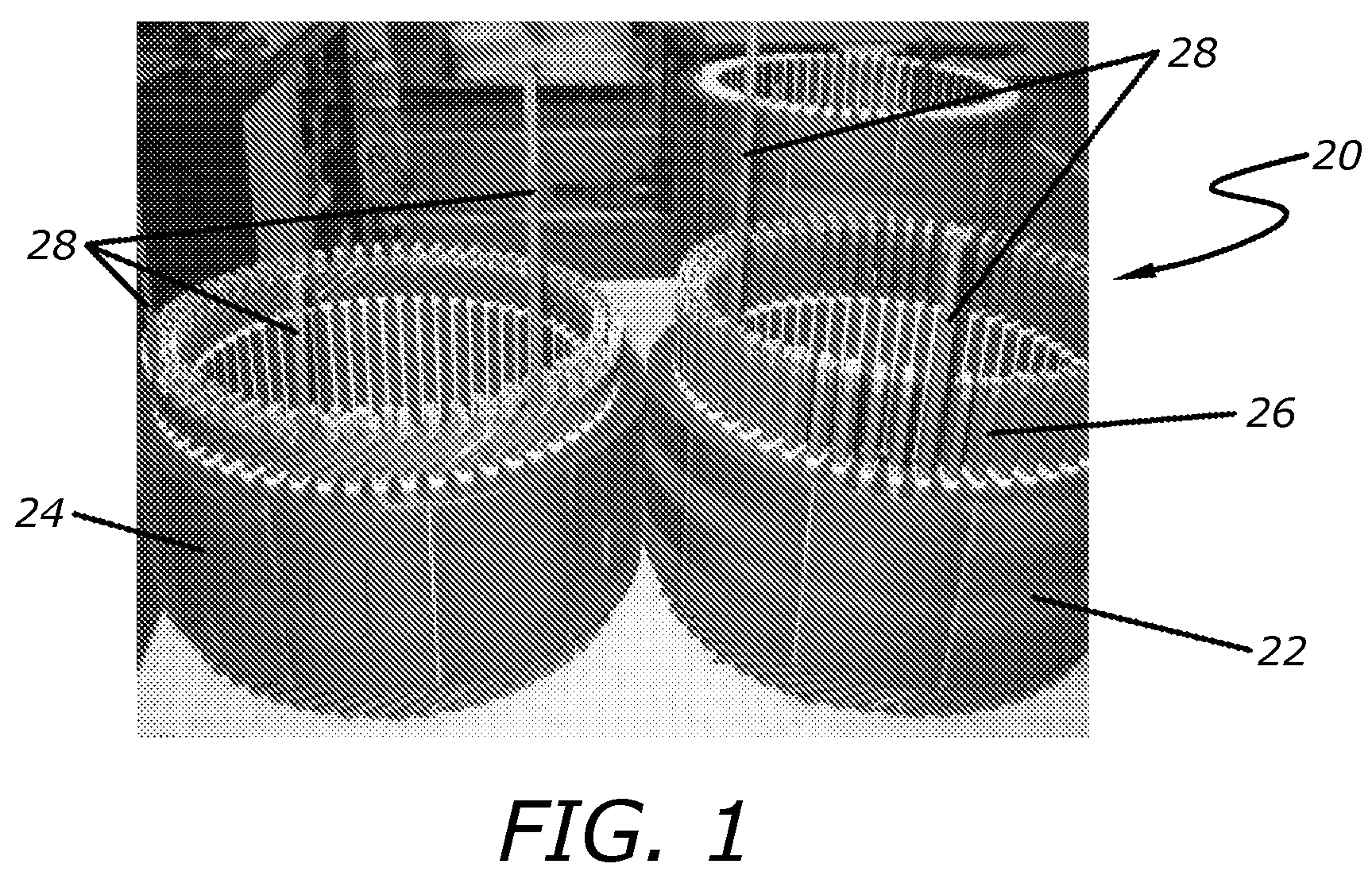
[0012]First referring to FIG. 1, three motor stators 20, 22 and 24 may be seen. Stator 20 in the background of the Figure is an insulated motor stator not yet populated with stator conductors. Stator 22, on the other hand, is populated with rectangular stator conductors 26. The lower ends of these stator conductors are bent so that an individual stator conductor spans a fixed number of stator slots, specifically, six stator slots in an exemplary embodiment. In a typical motor stator of the type described, certain stator conductors have one side thereof longer than the other conductors to provide terminal connections for the completed stator winding. In a three phase motor, three such longer stator conductors 28 are used, all three being visible in stator 24 of FIG. 1.

[0013]The purpose of the present invention is to provide a method for twisting the upper ends (referenced to the orientation of FIG. 1) of the stator conductors 26 as shown in stator 22 so that the ends of most of these...


PUM

PropertyMeasurementUnit
Lengthaaaaaaaaaa
Angleaaaaaaaaaa
Dimensionaaaaaaaaaa

Abstract

Methods and apparatus for twisting rectangular rotor and stator conductor ends whereby most if not all conductor ends are bent at once, radially adjacent ends being bent in opposite directions. A lost motion member may be used to bend selected conductors through lesser angles for such purposes as phase interconnection and power leads. The rectangular conductors are retained against twisting so that flat conductors will bend about an axis perpendicular to the larger dimension of the conductor cross section. Various features of the methods and apparatus are disclosed.

Description

BACKGROUND OF THE INVENTION[0001]1. Field of the Invention[0002]The present invention relates to the field of electric motors.[0003]2. Prior Art[0004]Tecnomatic S.p.A., assignee of the present invention, has in the past made a limited number of motor stators and D.C. motor rotors using flat or square wire for the windings. In that regard, it is to be noted that as used herein, “flat” or “square” wire means wire having four substantially flat sides, each joined to adjacent sides, typically by a rounded edge. In the case of square wire, the wire may be formed in the square shape and then coated with typical winding insulation, or in some cases, pre-coated round wire has been rolled into the square shape. Rolling of round wire to a square shape has definite limits if the insulation is not to be damaged, though smaller rounded edges may be achieved if the wire is first formed by drawing or otherwise formed into the square shape and then coated. Even if the wire is first formed in the de...

Claims


Application Information

Patent Timeline
IPC IPC(8): H02K15/08H02K15/00
CPCH02K15/0031H02K15/0428Y10T29/49009Y10T29/53161Y10T29/49012H02K15/0056H02K15/0087
Inventor GUERCIONI, SANTE
Owner TECNOMATIC
Why Eureka
Try Eureka