

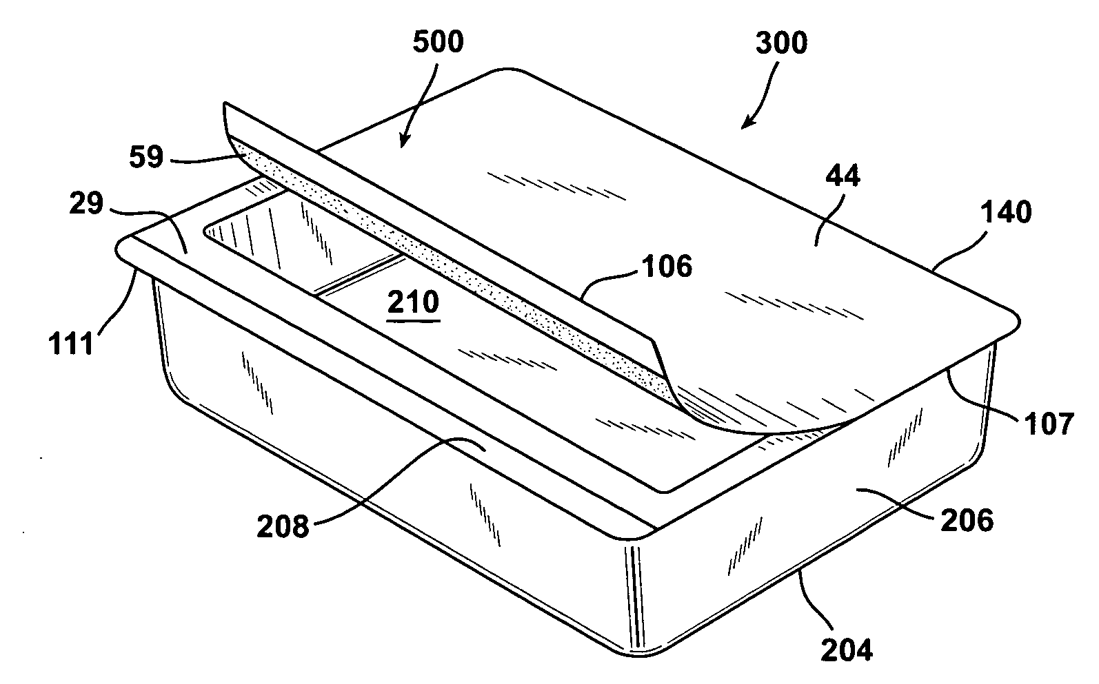
Laminated lidstock and package made therefrom
- Summary
- Abstract
- Description
- Claims
- Application Information
AI Technical Summary
Benefits of technology
Problems solved by technology
Method used
Image

Examples
examples
[0061]1. Material
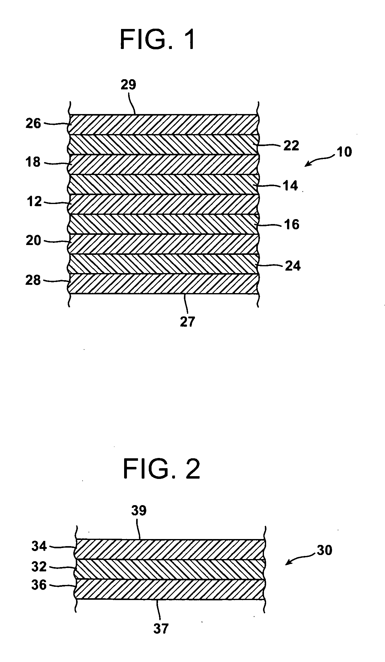
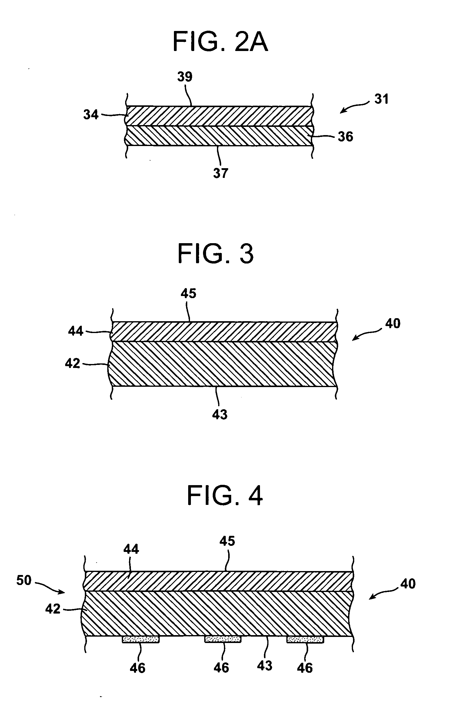
[0062]The lidstock laminate for use in accordance with the invention includes (a) a substrate film, and (b) a printed support web. Resins for these films are identified in Table 1.
TABLE 1MaterialTradename OrCodeDesignationSource(s)AD1PX3236 ™EquistarNY1AEGIS ™ H100QPHoneywellNY2GRIVORY ™ G21EMSNY3ULTRAMID ™ B33LN 01BASFOB1SOARNOL ™ ET3803Nippon GohseiOB2EVAL ™ H171BEVALCA / KurarayPE1EXCEED ™ 4518PExxonMobilPE2EXACT ™ 3024ExxonMobilSL1FSU 255E ™A. SchulmanSL2GRILON ™ MB 3361 FSEMSNaturalSL31080864S ™ClariantAD1 is a maleic anhydride grafted linear low density polyethylene that acts as a polymeric adhesive (tie layer material). It has a melt flow rate of 2.0 grams / 10 minutes at 190° C. / 02.16 kg (Condition E), and a density of 0.922 grams / cc.NY1 is nylon 6 (polycaprolactam).NY2 is an amorphous copolyamide (6I / 6T) derived from hexamethylene diamine, isophthalic acid, and terephthalic acid.NY3 is nylon 6 (polycaprolactam).OB1 is an ethylene / vinyl alcohol copolymer (EVOH) ...
PUM
| Property | Measurement | Unit |
|---|---|---|
| Thickness | aaaaa | aaaaa |
| Volume | aaaaa | aaaaa |
| Angle | aaaaa | aaaaa |
Abstract
Description
Claims
Application Information