
Massage implement

a technology of implements and massages, applied in the field of massage implements, can solve the problems of requiring a great physical effort on the part of the therapist, affecting the effectiveness of the massage work, and affecting the treatment effect of patients, etc., to achieve the effect of reducing the amount of pressure on the arms, wrists or hands

Inactive Publication Date: 2009-12-10
LUND MERRILL A
View PDF7 Cites 15 Cited by
  • Summary
  • Abstract
  • Description
  • Claims
  • Application Information

AI Technical Summary

Benefits of technology

[0009]An object of the tool or implement alleviate any undue pressures on the arms, wrists or the hands of a therapist. The tool is adjustable in length so that a practitioner with varying arm length can use. The implement is adjustable in length so that it can be used on various types of therapy tables, (adjustable or fixed in height) and so that various parts of the body of a patient can be reached with the table at the same height.
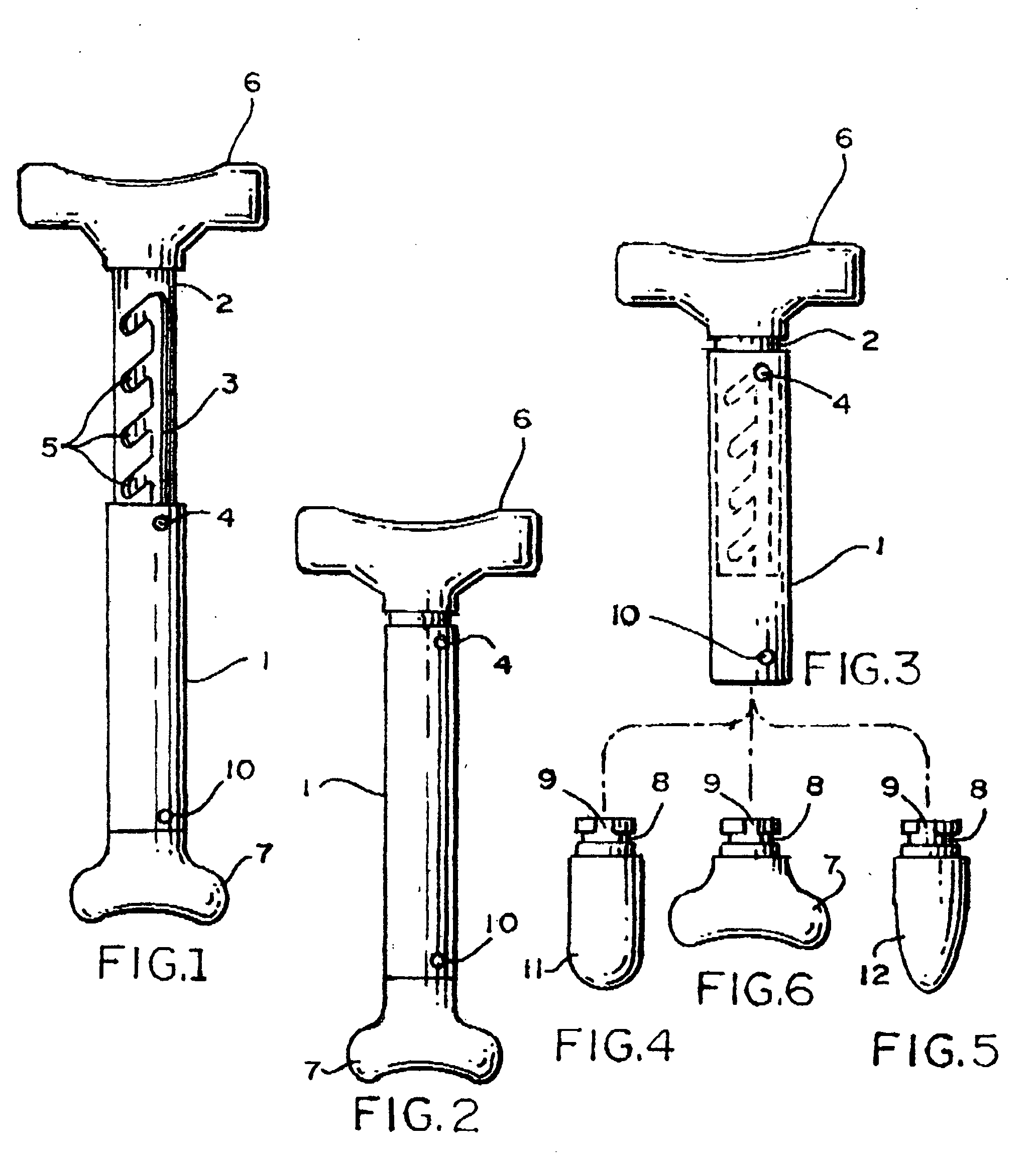
[0010]The tool has assorted and exchangeable body contacting tips intended for very specific work, that is, one tip for broad pressure over a large area, efflarage, fascia, doing legs etc. Other tips are useful and effective in treating general specific areas, such as, deep bodied muscles, specific knots on a large body muscle. There tips for general specific areas, deep bodied muscles, specific knots in a large muscle, etc. Another tool is designed for a very specific pressure along the lamina groove along the spine and specific trigger points.

Problems solved by technology

The problem is that in order to do deep effective work in a body massage takes a huge toll on the therapists bodies, especially their thumbs, wrists and / or arms.
This problem may lead to most therapists' use so many less effective treatment on their patients.
More neuromuscular type treatments are much more effective but require a on part of the therapist great physical effort, while may times causing injuries to the care giver.
The drawbacks of such a tool is that it uses its own weight to apply pressure and the therapists must use the hands, wrists or arms to hold the 8 lb. weight and guide it.
The risk of dropping the tool on a patient is a concern as well.

Method used


Image

  • Massage implement
  • Massage implement

Examples


Embodiment Construction

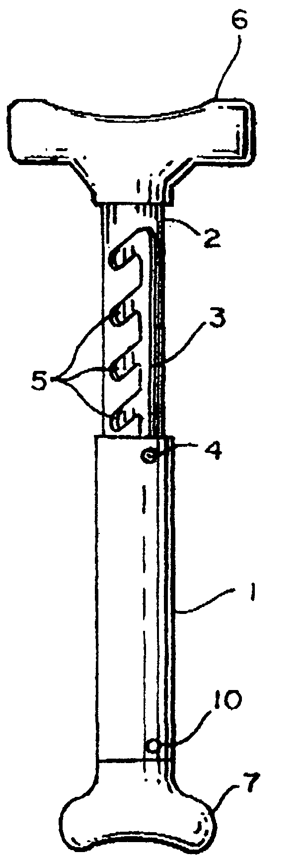
[0015]FIG. 1 shows the fully assembled massage implement 1. The implement consist of two major parts. There is a rigid metal tube 1 and a sliding insert 2 which could be made of hard rubber or a plastic material. The sliding insert has a longitudinal groove 3 therein which is held in a sliding relationship with the metal tube 1 by way of a pin or depression 4 in the bottom end of the tube 1. Along the groove 3 there are lateral exit grooves 5 which are slanted in a downward direction relative to the groove 3. The reason for this slanting is that once a certain groove has been selected, the pin or depression 4 will move into a selected lateral groove and will move in a downward direction. This way, when any downward pressure is applied to the implement, the pin or depression 4 cannot unlock itself from the longitudinal groove to thereby safely maintain a preselected position. The extending mechanism just described could be done by way of a spring-loaded peg and a series of holes. The...


PUM


Abstract

A massage implement consisting of two elements. One element is a metal tube that receives an adjustable insert therein. The insert and the tube are adjustable in length relative to each other. The metal tube has at its top a T-shaped configuration attached thereto which is made of a hard rubber or plastic material. The sliding insert is made of hard rubber or a plastic material and has a way of arresting the sliding insert therein after a predetermined length has been established. The sliding insert has at its bottom replaceable massaging tools thereon. The different massaging tools are used for treating different areas on the body of a patient. The massage implement is used by a therapist by placing the T-shaped configuration in the area of the armpit and by applying pressure to any of the bottom massage tools. The pressure is applied by the weight of the body of therapist.

Description

FIELD OF THE INVENTION[0001]The inventive implement relates to,an implement or a tool that is being used while given a massage to a person.BACKGROUND OF THE INVENTION[0002]There are many massage therapists, and most of them love their work, and many of them are highly educated and extremely effective at alleviating or removing pain syndromes.[0003]The problem is that in order to do deep effective work in a body massage takes a huge toll on the therapists bodies, especially their thumbs, wrists and / or arms. This problem may lead to most therapists' use so many less effective treatment on their patients.[0004]More neuromuscular type treatments are much more effective but require a on part of the therapist great physical effort, while may times causing injuries to the care giver. The biggest reason that massage therapists leave the profession, after a few year, is because of injury, wear and tear on their bodies. There are many tools available on the market to aid the therapists making...

Claims


Application Information

Patent Timeline
Patent Type & Authority Applications(United States)
IPC IPC(8): A61H7/00
CPCA61H2201/1685A61H7/003
Inventor LUND, MERRILL A.
Owner LUND MERRILL A
Learn More