Implant and implant system
a technology of implant and system, applied in the field of implants, can solve the problems that the known implant is not suitable for successively adjusting to the intervertebral disk, and achieve the effect of reducing the risk of infection
- Summary
- Abstract
- Description
- Claims
- Application Information
AI Technical Summary
Problems solved by technology
Method used
Image

Examples
first embodiment
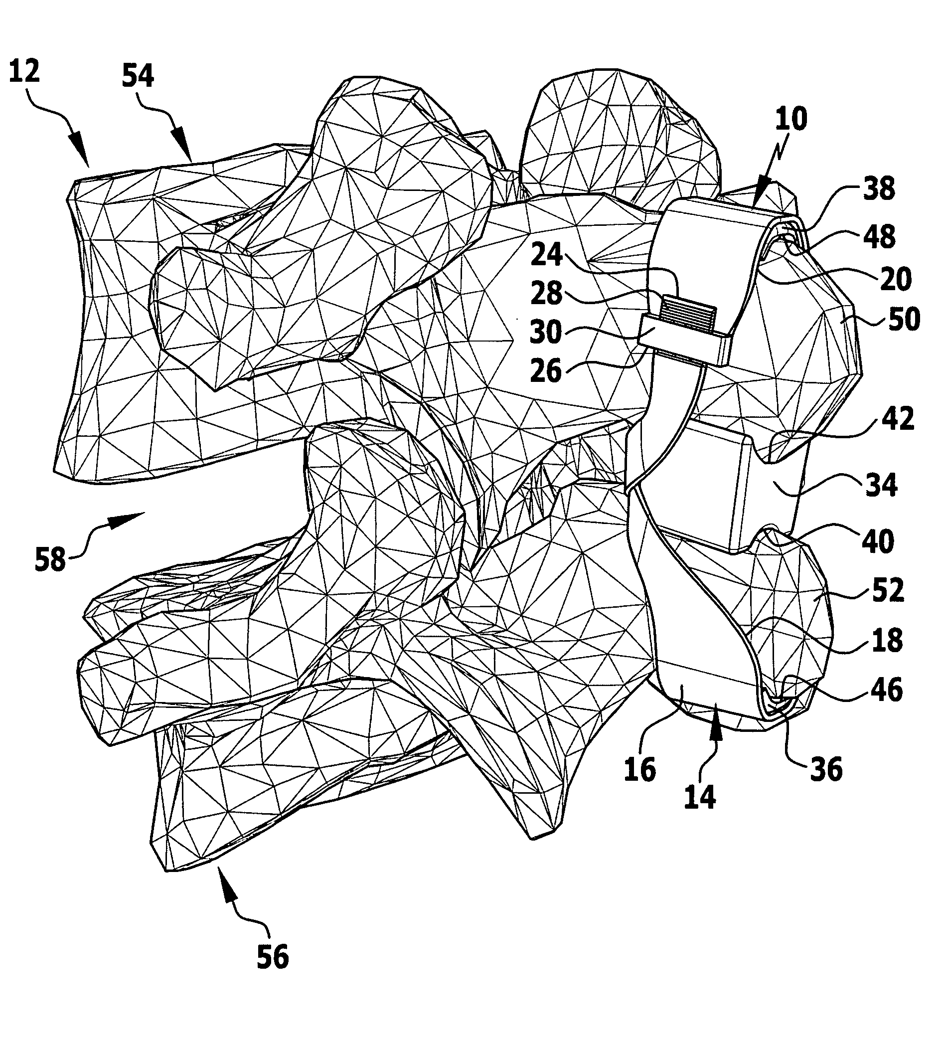
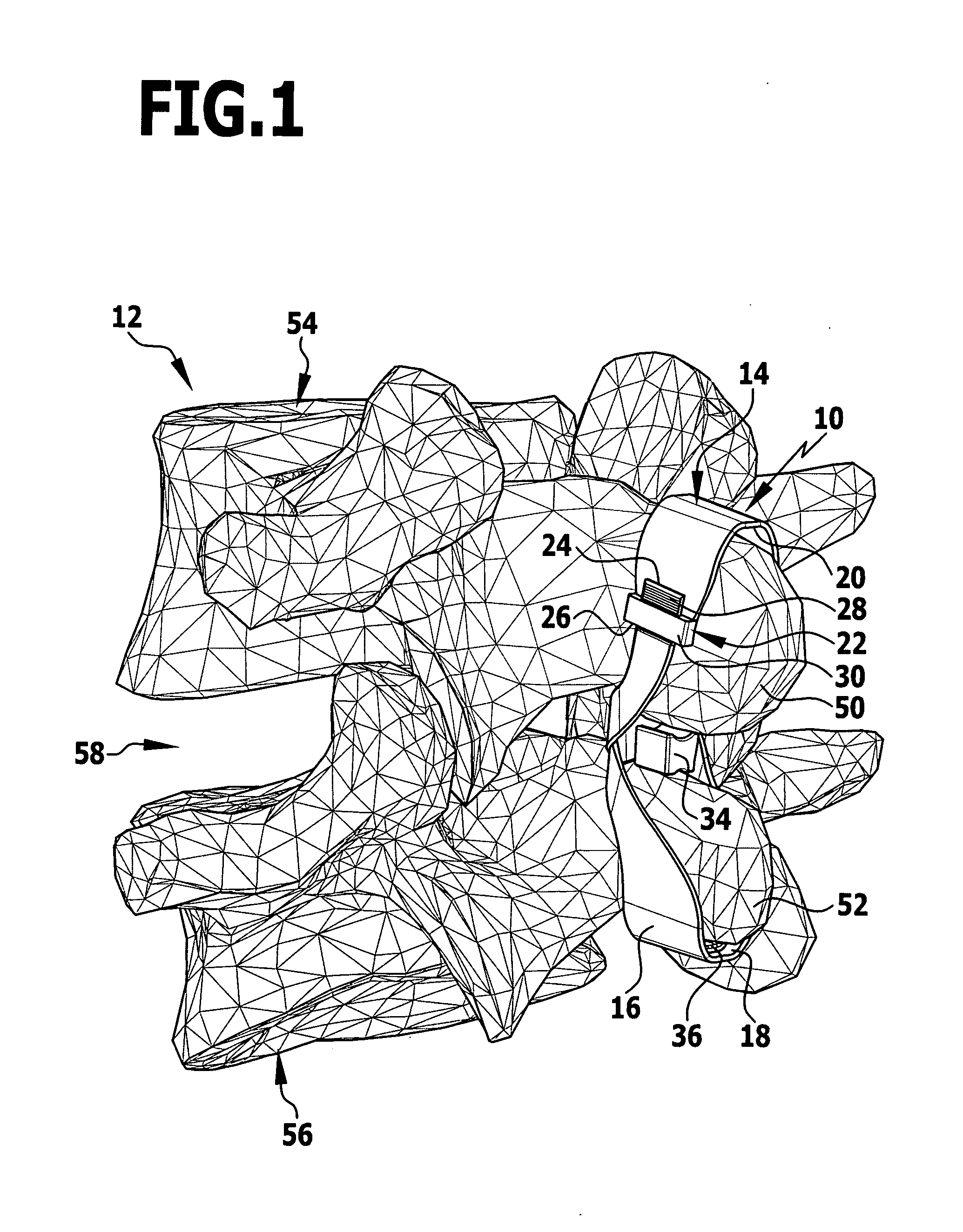
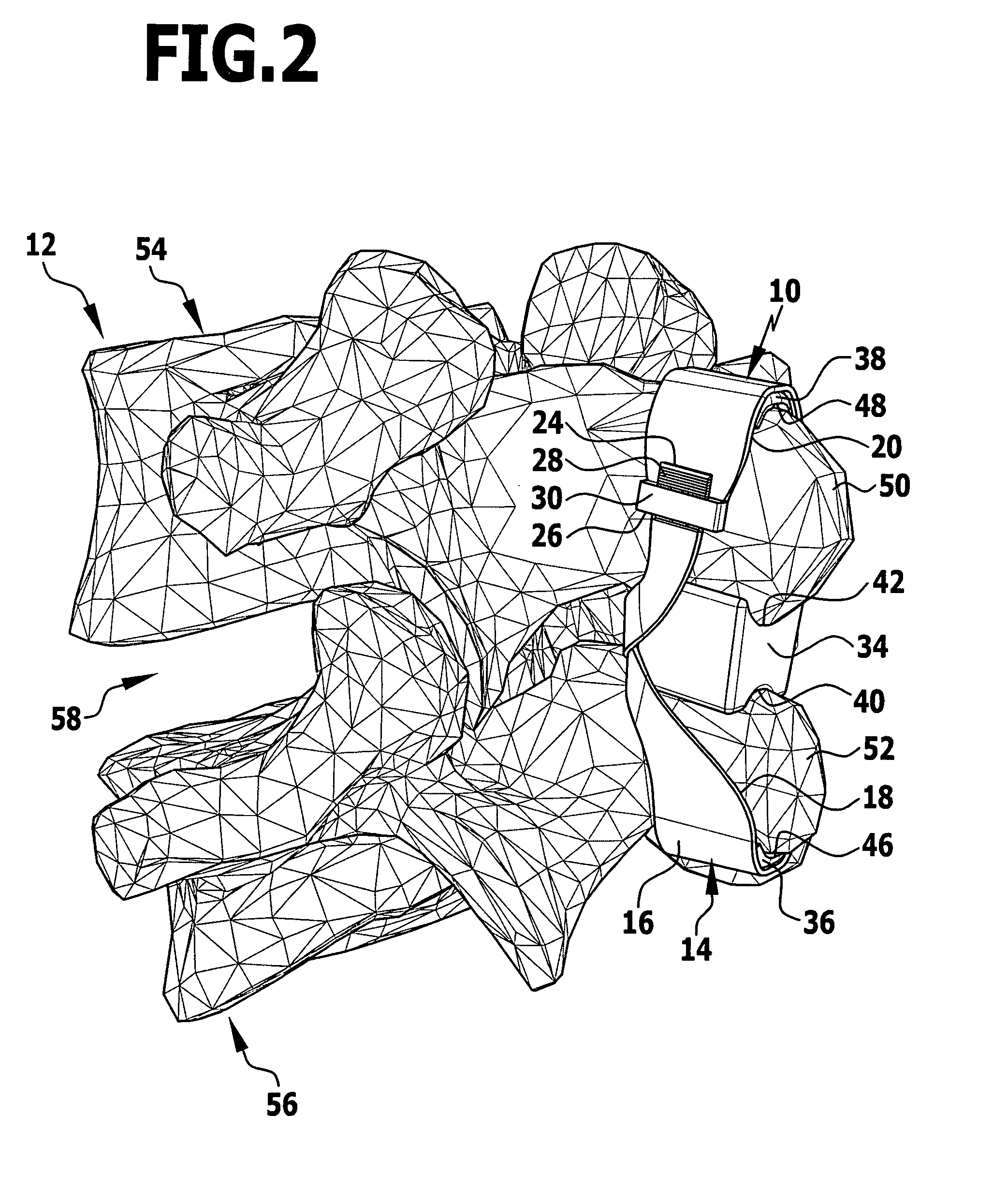
[0080]an implant for the dynamic dorsal stabilization of a human spinal column 12 is illustrated in FIGS. 1 to 4 and provided, altogether, with the reference numeral 10. It comprises an attachment device 14 in the form of a crossover tape 16 which is laid essentially in the form of an “8”.
[0081]The tape 16 laid or looped in the form of an “8” defines two spinous process receptacles 18 and 20 which are closed essentially in the shape of a ring. A closure device 22 is provided for closing the tape in the shape of a ring and connects free ends 24 and 26 of the tape 16 to one another. In the embodiment illustrated in FIGS. 1 to 4, the closure device 22 is designed in the form of a unidirectional closure device, namely in the form of a cable tie closure. For this purpose, the free end 24 is provided on one side with teeth 28 formed transversely to a longitudinal direction of the tape 16. A locking member 30 in the shape of a parallelepiped is placed on the other free end 26 and has an op...
third embodiment
[0096]an implant for the dynamic dorsal stabilization of a motion segment of the spinal column 12 is illustrated in FIGS. 6 to 11 and provided altogether with the reference numeral 110. Parts of the implant 110, which are of the same design or essentially the same design as parts of the implants 10 and 70, are provided with reference numerals which have the same two end numbers.
[0097]The implant 110 comprises an attachment device 114 which corresponds essentially to the attachment device 14. It comprises a tape 116 which can loop around the spinous processes 50 and 52 with its inner side 144 and be fixed to them. However, the tape 116, in contrast to the tape 16, is fixed to a central spacer element 134 at two attachment points 180 and 182. An upper part of the tape 116 runs around the spinous process 50, proceeding from the attachment point 180, in an anticlockwise direction when seen dorsally as far as the attachment point 182 which is provided on the spacer element 134 at the sam...
PUM
 Abstract
Description
Claims
Application Information
 - R&D
- Intellectual Property
- Life Sciences
- Materials
- Tech Scout
- Unparalleled Data Quality
- Higher Quality Content
- 60% Fewer Hallucinations
Browse by: Latest US Patents, China's latest patents, Technical Efficacy Thesaurus, Application Domain, Technology Topic, Popular Technical Reports.
© 2025 PatSnap. All rights reserved.Legal|Privacy policy|Modern Slavery Act Transparency Statement|Sitemap|About US| Contact US: help@patsnap.com