Retaining wall block

a technology for retaining walls and blocks, applied in the field of retaining wall blocks, can solve the problems of limiting the number of blocks which can be formed on the pallet, molds to work improperly, and production pallets occupy considerable spa

Inactive Publication Date: 2009-12-17
KEYSTONE RETAINING WALL SYST
View PDF23 Cites 64 Cited by
  • Summary
  • Abstract
  • Description
  • Claims
  • Application Information

AI Technical Summary

Problems solved by technology

There are several disadvantages with this process of forming retaining wall blocks.
First, since mold boxes and production pallets come in typical sizes the orientation of the blocks with their top surfaces on the production pallets takes up considerable space and limits the number of blocks which can be formed on a pallet during a production cycle.
However, this mold box has several disadvantages.
These moving side walls may become plugged with the moldable material or otherwise malfunction causing the mold to work improperly.
Second, during the block manufacturing process if the flange-forming sub cavity is not completely filled with material or properly cleaned between mold cycles the flange may not be properly or completely formed on the block.
Third, the orientation of the front face of the block at the open top of the mold box prohibits the blocks formed in the mold from being provided with a core.

Method used


Image

  • Retaining wall block
  • Retaining wall block
  • Retaining wall block

Examples


Embodiment Construction

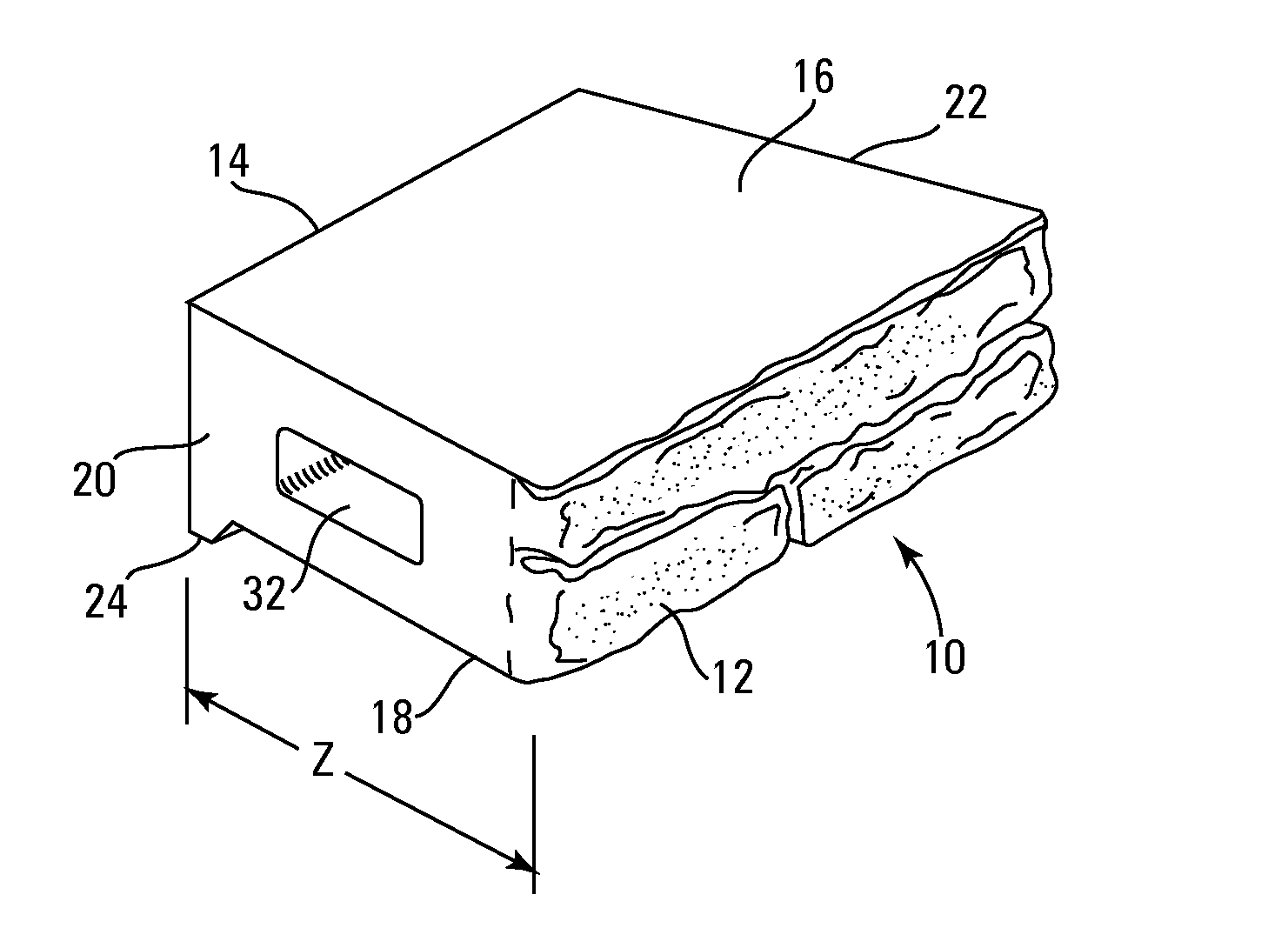
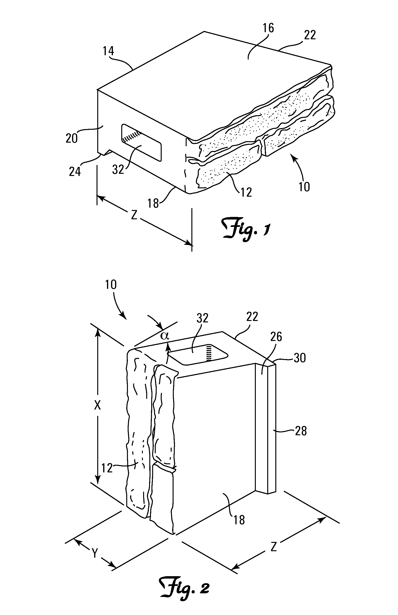
[0029]A retaining wall block 10 according to the present invention is shown in perspective in FIGS. 1 and 2. Block 10 comprises a block body defined by opposed front and rear faces 12 and 14, respectively. The front and rear faces are substantially parallel and are separated by a distance Z which comprises the depth of the block. The depth of the block is determined by the size of the mold in which the block is formed as will be described in more detail hereafter. Typically, the depth will be in the range of about 5 to 9 inches. The block body includes opposed top and bottom surfaces 16 and 18, respectively. The top and bottom surfaces are substantially parallel and separated by a distance Y which comprises the thickness or height of the block. The block thickness is determined by the size of the mold and for a typical block may be 4 inches. The block body includes opposed first and second side surfaces 20 and 22, respectively. The first and second side surfaces are not parallel to ...


PUM

PropertyMeasurementUnit
angleaaaaaaaaaa
angleaaaaaaaaaa
depthaaaaaaaaaa

Abstract

A retaining wall block having a rear flange and a mold box and method of making the block. The mold box is configured with a mold cavity that includes a vertical flange forming cavity extending from the top of the mold box to the bottom of the mold box.

Description

[0001]This application is a continuation of U.S. Ser. No. 12 / 252,837, filed Oct. 16, 2008, which claims the benefit of U.S. Provisional Application No. 60 / 980,886, filed Oct. 18, 2007, entitled “Retaining Wall Block”, the contents of each of which are hereby incorporated by reference herein.FIELD OF THE INVENTION[0002]The present invention relates generally to retaining wall blocks and retaining walls constructed from such blocks. Additionally, the invention includes block molds and methods of manufacturing the blocks.BACKGROUND OF THE INVENTION[0003]Retaining walls are used in various landscaping projects and are available in a wide variety of styles. Numerous methods and materials exist for the construction of retaining walls. Such methods include the use of natural stone, poured concrete, precast panels, masonry, and landscape timbers or railroad ties. In recent years, segmental concrete retaining wall units, which are dry stacked (i.e. built without the use of mortar), have beco...

Claims


Application Information

Patent Timeline
Patent Type & Authority Applications(United States)
IPC IPC(8): E04C2/04E02D17/18E04B1/00E02D17/00
CPCB28B7/0041B28B7/0073B28B7/0097B28B7/183B28B7/24B28B3/02E04B2002/0208E04B2002/0263E04B2002/0267E04C1/395E02D29/025
Inventor MACDONALD, ROBERT A.LACROIX, DAVID M.
Owner KEYSTONE RETAINING WALL SYST
Why Eureka
Try Eureka