
Humidification control unit and method of manufacturing same

a technology of humidity control unit and humidity control unit, which is applied in the direction of air humidification system, lighting and heating apparatus, heating types, etc., can solve problems such as reducing humidification performan

Inactive Publication Date: 2001-03-13
KK METRAN
View PDF114 Cites 59 Cited by
  • Summary
  • Abstract
  • Description
  • Claims
  • Application Information

AI Technical Summary

Benefits of technology

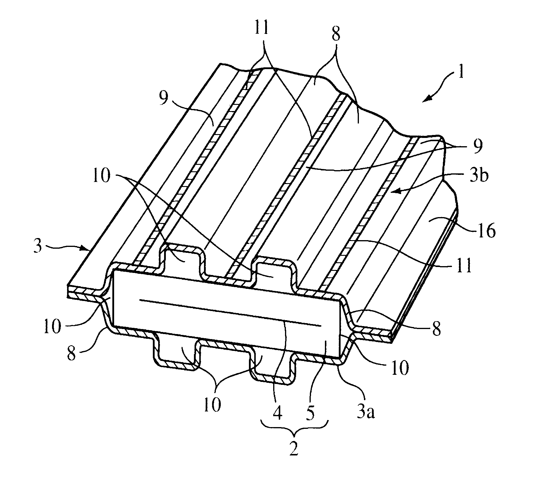
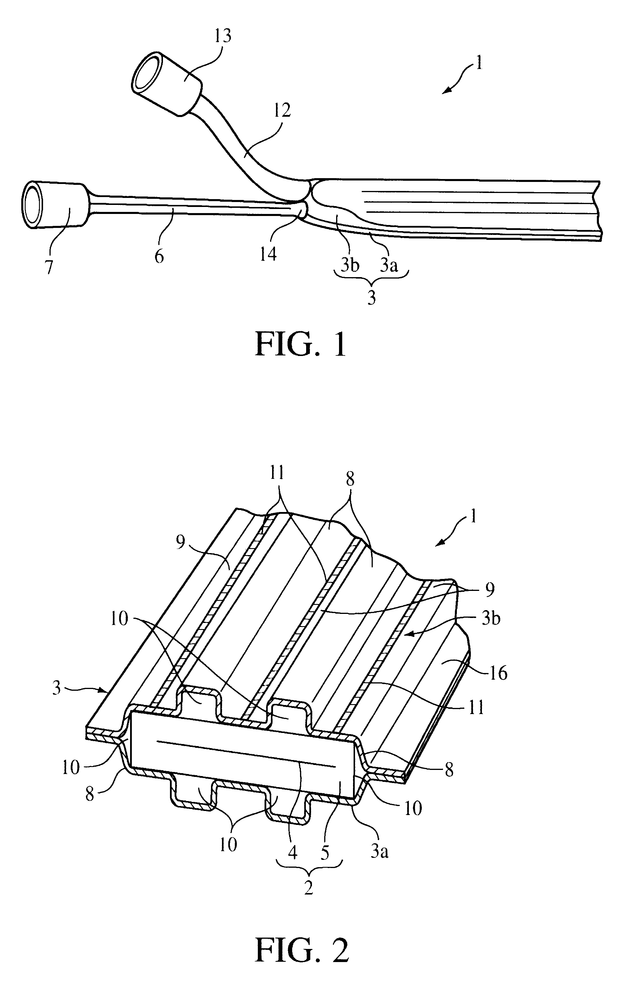
The above-mentioned covering and the outer wall of the above-mentioned heating element are bonded to define water routes between the bulges in the heating element. The open side of the above-mentioned covering is then covered by the abovementioned cap. Because a heating element is housed in a covering that has a porous retaining wall through which water does not pass but steam passes and independent water routes are formed between the outer wall of the heating element and the covering by cooperative action between the outer wall of the heating element and the covering by providing spaces along the circumference of the heating element, when water is supplied into each water route and heated by the heating element, steam is expelled from each water route through the porous retaining wall, and the desired humidifying performance can be achieved under optimum conditions.
In addition, because the outer surface of the heating element is used as part of the wall of the water routes and the heating element does not have to be housed inside the water routes, the size of the heating element does not restrict making the cross section of each water route as small as possible. As a result, even if the covering breaks or is damaged, the amount of water leaking from the water routes that this covering covers is minimized, and water leakage can be reduced to the extent that there is no substantial decrease in humidifying performance or problems associated with excessive water leakage.
Because the humidifying unit in one embodiment of this invention has several bulges in the covering along the circumference of the heating element that protrudes outward from the outer surface of the heating element, each water route is comprised of a bulge and the outer surface of the heating element that covers the open base end of the bulge. In addition to having the desirable leak minimization effects described above, the surface area of the steam emitting surface is increased by each bulge, and humidifying performance is improved.
In another embodiment of the present invention, channels are formed in the outer surface of the heating element by providing spaces along the circumference of the heating element. In this embodiment, each water route is defined by the channel and the covering that covers the opening of the channel. In addition to having the desirable leak minimizing effects described above, the proportion of the outer wall of the heating element that comprises the side walls of each water route is increased, and by making the shape of the water routes more stable, the stability of humidifying performance can be increased. As a result, this humidity regulating unit can be used in regions that have higher speed flow.
In yet another embodiment of the present invention, the covering and the outer surface of the heating element are bonded between adjacent water routes, the independence of each water route can be assured and the leak minimizing effects described above can be achieved more securely.
The present invention also contemplates that the outer surface of the heating element is formed by a coating resin and the covering is welded to the coating resin of the heating element. By taking advantage of the easy bonding between these two (the covering generally is formed by a resin such as polytetrafluoroethylene), the covering and the outer surface of the heating element can be bonded easily.

Problems solved by technology

If the water carrying tube is broken, an impermissible amount of water inevitably leaks which can cause various problems.
When the humidity regulating unit is used in the inhalation route of an artificial respirator, for example, water leakage has the undesirable effect of reducing humidifying performance and the leaking water itself can flow to the inhalation side of the inhalation circuit, which is the side where the user of the artificial respirator is located.

Method used


Image

  • Humidification control unit and method of manufacturing same
  • Humidification control unit and method of manufacturing same
  • Humidification control unit and method of manufacturing same

Examples


first embodiment

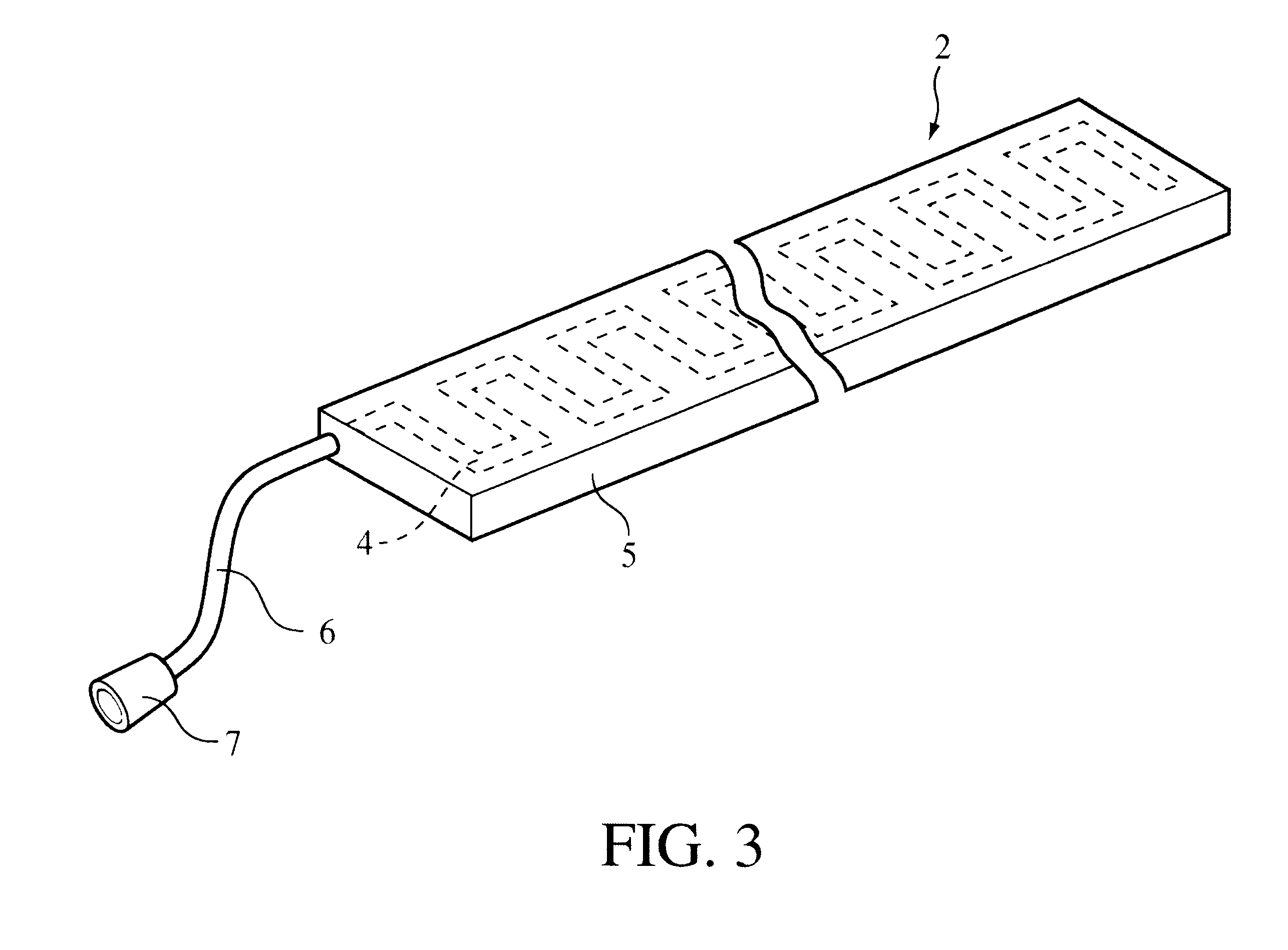
FIGS. 1 to 5 show a humidity regulating unit. The humidity regulating unit is installed inside an inhalation tube (not shown) for example near the patient of an inhalation circuit. For adult use, a tube with a diameter of about 22 mm is used in an artificial respirator to connect the patient's lungs (not shown) to an inhalation gas supply source (also not shown). Humidity regulating unit 1 includes a heating element 2 and a covering 3. The size of the humidity regulating unit 1 is, for example, about 18 to 20 mm in horizontal width, about 2 to 3 mm in thickness, and about 1 m in total length.

In this embodiment, as shown in FIG. 3, heating element 2 is a thin plate that has an extended shape with a rectilinear cross section, and has flat sides. Heating element 2 is an electric heating element, and to satisfy this electrical structure, heating element 2 includes a heating wire 4 (heater wire) and an insulator 5 that encloses the heating wire. Heating wire 4 is disposed inside insulato...

third embodiment

In this third embodiment, instead of using two halves 3a and 3b for covering 3", as in the first mode of embodiment described above, a single sheet is used for covering 3". The sheet is wrapped around heating element 2, and in addition to bonding portions 9 to the outer surface of heating element 2, ends 19 where the wrapping meets also are bonded. By using a single sheet as covering 3", part control and assembly operations can be simplified.

In the second and third embodiments described above, to maintain the independence of each water route 10, a structure is preferred in which heating element 2, 2' is placed tightly (i.e. in a watertight manner) within covering 3', 3". Furthermore, covering 3', 3" and heating element 2, 2' also can be bonded between adjacent water routes 10 as shown in the first embodiment (bonding sites 11).


PUM


Abstract

A humidity regulating unit including a heating element housed inside a covering that has a porous retaining wall through which water does not pass but steam or gas passes. In one embodiment, the covering has several bulges along the circumference of the heating element that protrudes outward from the outer surface of heating element to form several water routes along the outer surface of heating element. The covering and the outer surface of heating element are bonded between adjacent water routes so that the outer surface of heating element is used as part of the wall of the water routes. As a result, the size of heating element does not restrict making the cross section of each water route as small as possible, and even if the covering breaks, the amount of water leaking from the humidity regulating unit is minimized.

Description

1. Field of the InventionThis invention pertains to a humidity regulating unit and to a method of manufacturing a humidity regulating unit.2. Description of the Related ArtJapanese Unexamined Patent Appl. No. 62-26076 discloses a humidity regulating unit in which a tube is used to carry water over a heating element. The tube has a porous retaining wall as the main wall through which water does not pass but steam passes. This humidity regulating unit is designed such that an electric heating element (with a diameter of at least 3 mm) is arranged inside the tube by preparing one tube with a somewhat large diameter. During use, this water carrying tube is connected to a water supply source such that the tube is always filled with water. Steam is expelled through the porous retaining wall of the water carrying tube by the heat of the electric heating element.When this type of humidity regulating unit is used inside the inhalation route (inhalation circuit) of an artificial respirator, f...

Claims


Application Information

Patent Timeline
IPC IPC(8): F24F6/02A61M16/16
CPCA61M16/1075A61M16/16F24F6/025F24F6/10F24F2003/1435A61M16/142F24F6/00
Inventor NITTA, KAZUFUKU
Owner KK METRAN
Learn More