Gold evaporative sources with reduced contaminants and methods for making the same

a technology of evaporative sources and contaminants, applied in the field of gold evaporative sources, can solve the problems of device malfunction, lower production yield, and detriment to film quality, and achieve the effects of reducing surface contaminants, cross sectional, and altering surface roughness

Active Publication Date: 2017-10-31
PRAXAIR ST TECH INC
View PDF15 Cites 0 Cited by
  • Summary
  • Abstract
  • Description
  • Claims
  • Application Information

AI Technical Summary

Benefits of technology

[0008]In a first aspect, a gold evaporative source with reduced surface contaminants is provided that is prepared by a process comprising the steps of: providing a predetermined volume of gold evaporative sources, each consisting essentially of at least 99.999 wt % gold (5N Au), and further wherein each gold evaporative source is characterized by one or more surfaces extending between a first face and a second face; burnishing the gold evaporative sources against each other in the presence of a liquid slurry at ambient temperature under a controlled vibratory action, thereby loosening and removing at least a portion of contaminants along at least one of the first face, the second face and the one or more surfaces to form a partially cleaned gold evaporative source; followed by leaching the partially cleaned gold evaporative sources with boiling nitric acid to dislodge and remove contaminants along at least one of the first face, the second face or the one or more surfaces without substantially altering the surface roughness along the one or more surfaces, the first face, and the second face.
[0009]In a second aspect, a method for making gold evaporative sources with reduced surface contaminants comprising: providing a cast billet consisting essentially of at least 99.999 wt % gold (5N Au); subjecting the cast billet to one or more metal forming operations whereby a cross sectional diameter of the cast billet is reduced to create drawn wire; coiling the drawn wire; slicing the drawn wire to form gold evaporative sources each of which is characterized by one or more surfaces extending between a first face and a second face; burnishing the gold evaporative sources against each other in the presence of a liquid slurry at ambient temperature under a controlled vibratory action, thereby loosening and removing at least a portion of contaminants along at least one of the first face, the second face and the one or more surfaces to form a partially cleaned gold evaporative source; and leaching the partially cleaned gold evaporative sources with boiling nitric acid to dislodge and remove contaminants along at least one of the first face, the second face or the one or more surfaces without substantially altering the surface roughness along the one or more surfaces, the first face, and the second face.

Problems solved by technology

This phenomenon is known as “spitting” and is recognized as detrimental to film quality by virtue of the creation of in-film defects known as nodules or particles contained or embedded within the deposited gold film.
Such nodules are further problematic as they can significantly lower production yields and lead to device malfunction by a breakdown of the layered structures of the device.
Although such process conditions and parameters can be adjusted, spitting remains a prevalent problem during the gold evaporative process 100.
Additionally, end-users are often limited in their degree of freedom to alter conditions and parameters from established set points or target values.
However, the problem of inadvertent liquid droplet ejection from the crucible still occurs.

Method used


Image

  • Gold evaporative sources with reduced contaminants and methods for making the same
  • Gold evaporative sources with reduced contaminants and methods for making the same
  • Gold evaporative sources with reduced contaminants and methods for making the same

Examples


example 1

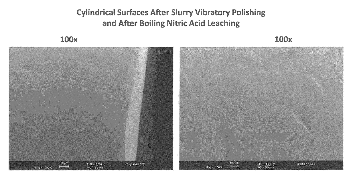
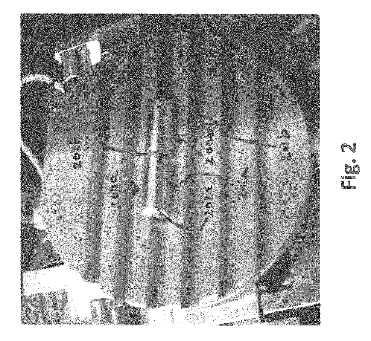
[0053]The as-sliced gold evaporative sources shown in FIG. 2, and by SEM images in FIGS. 3a, 3b, 4a and 4b were subject to a cleaning protocol in accordance with the principles of the present invention.

[0054]The gold evaporative sources were placed in a non-plastic container and then wrapped as shown in FIG. 5. The vibratory slurry polishing procedure as shown in FIG. 5 was utilized to remove surface contaminants and deburr and smoothen the edges, which are believed to act as preferential sites for carbon segregation. The vibratory polishing step involved usage of a liquid slurry (#2 Liquid Burnisher from Ultramatic Equipment Co.) and mechanical agitation within the vibratory tumbling mill of FIG. 5 at a frequency of 1000 min−1. In addition to deburring, it was observed that the mechanical agitation dislodged and removed contaminants from the gold surfaces as a result of the rubbing action of neighboring gold evaporative sources. The vibratory tumbling mill was operated for approxim...


PUM

PropertyMeasurementUnit
lengthaaaaaaaaaa
diameteraaaaaaaaaa
frequencyaaaaaaaaaa

Abstract

A unique sequence of steps is provided to reduce contaminants along one or more surfaces and faces of gold evaporative sources without deleteriously impacting the structure of the gold evaporative sources. Edges are deburred; contaminants are successfully removed therealong; and surface smoothness is substantially retained. The resultant gold evaporative source is suitable for use in evaporative processes as a precursor to gold film deposition without the occurrence or a substantial reduction in the likelihood of spitting by virtue of significantly reduced levels of contaminants, in comparison to gold evaporative sources subject to a standard cleaning protocol.

Description

FIELD OF THE INVENTION[0001]The present invention relates to gold evaporative sources with reduced residual surface contaminants and a unique method for removing such contaminants.BACKGROUND OF THE INVENTION[0002]Evaporation is a thin-film deposition process utilized for creating thin-film layers of gold onto a wafer. FIG. 1 shows a representative example of an evaporative process 100 for depositing thin-film layers of gold. The tool utilized in the process 100 is commonly referred to as a planetary evaporation tool 101. Solidified gold material 102 (refer to hereafter as a “gold evaporative source”) is placed in a crucible 103. Electron beam or resistance heating elements can serve as the heat source 104 to melt the gold evaporative source 102. The melting of the gold evaporative source 102 creates a liquid pool 105 as shown in FIG. 1. The gold evaporative source in molten form is further heated until vaporization occurs. The gold vapor traverses upwards within the interior of the ...

Claims


Application Information

Patent Timeline
Patent Type & Authority Patents(United States)
IPC IPC(8): B21C1/00C23G1/10C23C14/56C23C14/14B24B39/00B24B31/06C22B9/14C22C5/02B08B3/10B08B3/12B08B3/08B21C47/02C23C14/24C22B3/00
CPCB21C1/00C23G1/10B08B3/10B08B3/12B21C1/003B21C47/02B24B31/06B24B39/00C22B9/14C22B11/04C22C5/02C23C14/14C23C14/24C23C14/564B08B3/08
Inventor STUBER, WENDELL R.AVILES, ERNESTOSARKAR, JAYDEEPGILMAN, PAUL S.
Owner PRAXAIR ST TECH INC
Why Eureka
Try Eureka