
Hot-film air-mass meter having a flow separating element

a technology of air mass meter and flow separation, which is applied in the direction of liquid/fluent solid measurement, instruments, structural/machine measurement, etc., can solve the problems of contaminating the sensor chip, oil for example, and affecting the accuracy of the measurement, so as to reduce the instabilities of the signal and reduce the surface contamination

Inactive Publication Date: 2013-05-28
ROBERT BOSCH GMBH
View PDF17 Cites 3 Cited by
  • Summary
  • Abstract
  • Description
  • Claims
  • Application Information

AI Technical Summary

Benefits of technology

The design significantly reduces surface contamination and signal instabilities, maintaining signal stability and reducing the risk of faults, resulting in a more robust and reliable air-mass flow measurement system.

Problems solved by technology

DE 101 11 840 C2, with this type of sensor is, however, that contamination of the sensor chip, by oil for example, often occurs.
This oil deposit may result in undesirable effects on the measuring signal of the sensor chip, in particular because an oil film affects the thermal conductivity of the sensor chip surface, which results in corruption of the measuring signals or a signal drift.
This is one of the reasons why, when operating a thermal air-mass flow meter at the border region of the heated measuring areas, liquids such as oil accumulate and over time result in a drift of the measuring signal of the hot-film air-mass meter.
In addition to the oil droplets, other contaminants (e.g., dust) also reach the surface of the measuring area due to this effect.
This effect, whereby oil and other contaminants are driven onto the surface of the measuring area in irregular intervals, causes short-term and unpredictable signal instabilities of the hot-film air-mass meter in particular.
These are caused, in particular, by the sporadically occurring contamination modifying the thermal conductivity of the surface of the measuring area, whereby a previously performed calibration of the hot-film air-mass meter becomes invalid.
In addition to short-term changes, longer-lasting changes of the signal characteristic of the hot-film air-mass meter may also occur in particular if the contamination driven onto the measuring surface adheres there for a longer time.
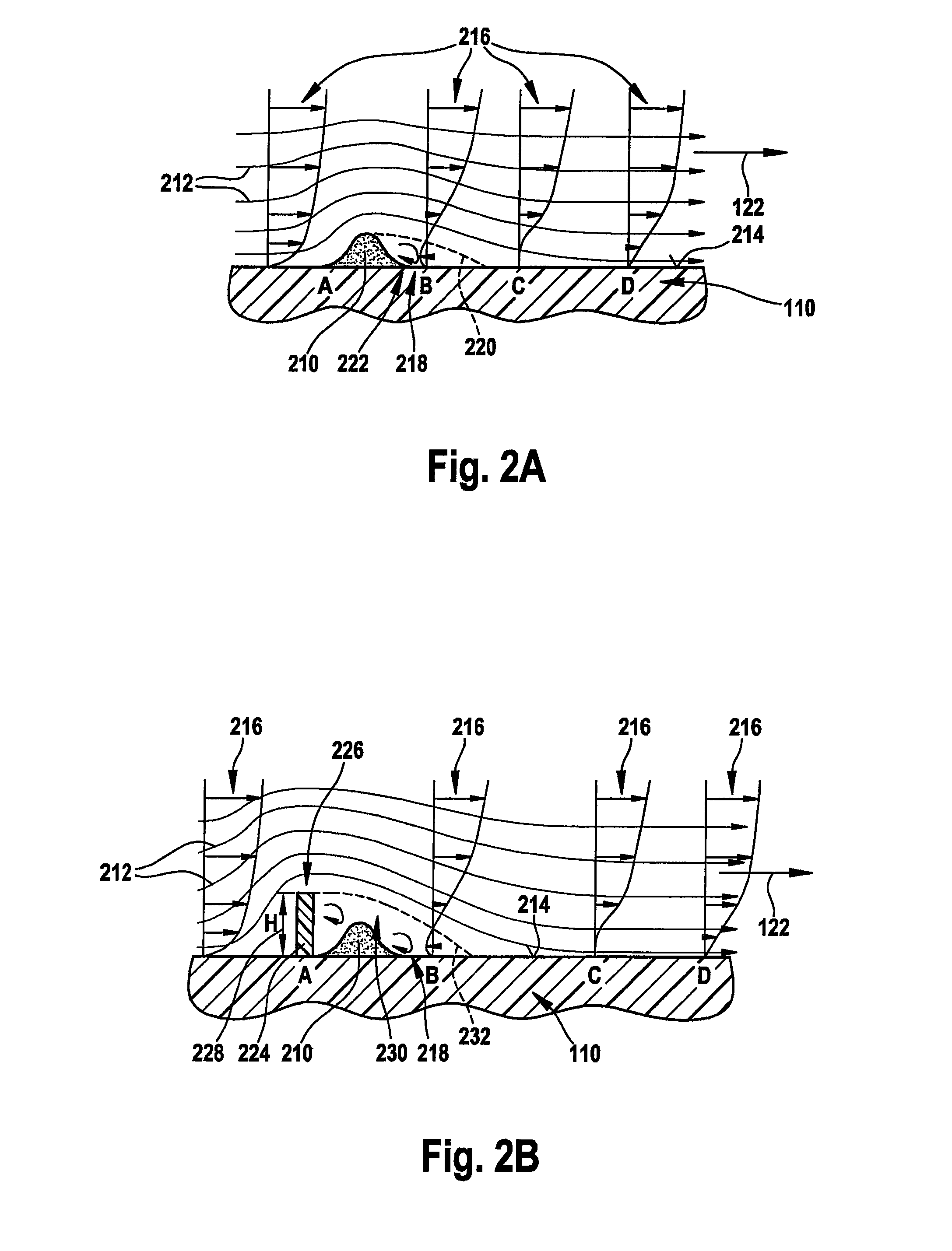
Another problem arising from contamination accumulating in particular on the boundary of the measuring area is the effect on the flow dynamics of the hot-film air-mass meter.
If, however, contamination, in particular a liquid wall, accumulates on the boundary surface of the measuring area during operation, it also affects the velocity profile of the air-mass flow over the measuring surface and thus the temperature profile.
Since, however, the heat transport on the measuring surface is a function of the shape of the velocity profile and temperature profile, this results in a signal drift of the hot-film air-mass meter.
This in turn may result in a signal drift.
If the at least one flow separating element is too far upstream from this boundary line, this results in the flow again being in contact with the chip surface when it reaches the contaminants on the boundary line.

Method used


Image

  • Hot-film air-mass meter having a flow separating element
  • Hot-film air-mass meter having a flow separating element
  • Hot-film air-mass meter having a flow separating element

Examples


Embodiment Construction

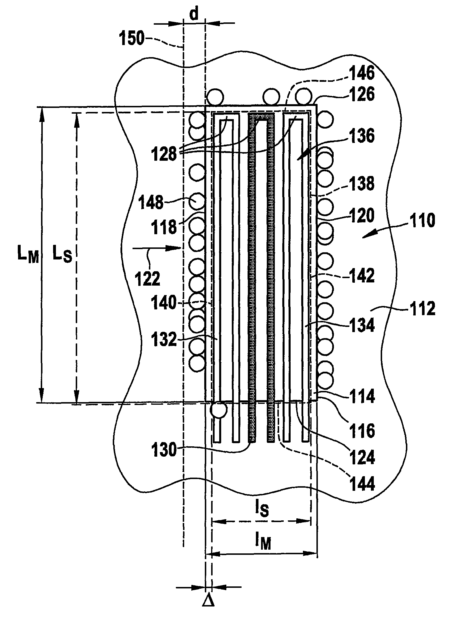
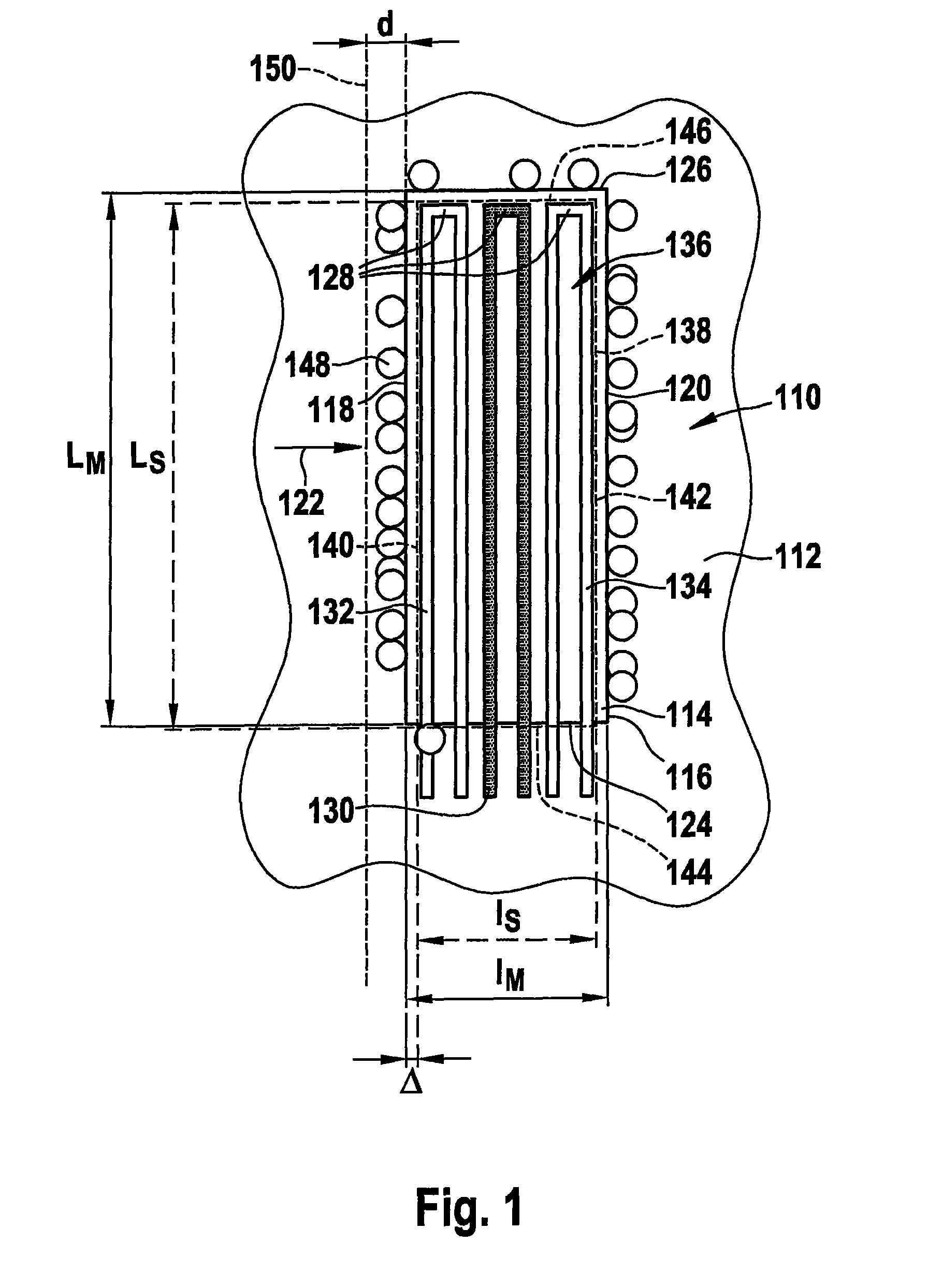
[0027]FIG. 1 shows a design of a sensor chip 110 (only indicated) of a conventional hot-film air-mass meter (except for a flow separating element according to the present invention, see below). Sensor chip 110 may be used, for example, in the intake tract of an internal combustion engine or in a bypass channel to the intake tract of an internal combustion engine. German Patent Application No. DE 196 01 791 A1, for example, describes devices of this type. The sensor chip of the embodiment of FIG. 1 has a main chip area having a main chip area surface 112 in the plane of the drawing (illustrated schematically only). In this exemplary embodiment it is assumed that sensor chip 110 is a silicon sensor chip. Furthermore, sensor chip 110 has a measuring area having a measuring surface 114 in the plane of the drawing. In this exemplary embodiment, measuring surface 114 is designed in the shape of a rectangle 116, which has longer sides LM 118, 120 perpendicular to a main flow direction 122 ...


PUM


Abstract

A hot-film air-mass meter for measuring an air-mass flow which flows in the main direction of the flow, which can be used, in particular, in the intake tract of an internal combustion engine. The hot-film air-mass meter comprises a sensor chip having a measuring surface. The air-mass flow flows essentially parallel over one surface of the sensor chip. A flow separating element is mounted upstream from the measuring surface with respect to the main flow direction. The at least one flow separating element is designed in such a way that the air-mass flow is separated from the measuring surface of the sensor chip in at least one separation zone prior to reaching the measuring surface.

Description

FIELD OF THE INVENTION[0001]The present invention relates to a hot-film air-mass meter having a flow separating element for preventing surface contamination and signal drift due to surface contamination. Such hot-film air-mass meters are used in particular for measuring air-mass flows in the intake tract of internal combustion engines.BACKGROUND INFORMATION[0002]In many processes, for example, in the area of process engineering, chemistry, or mechanical engineering, a well-defined gas mass, in particular an air mass, must be supplied. This includes in particular combustion processes, which take place under controlled conditions. One important example is the combustion of fuel in internal combustion engines of motor vehicles, in particular having downstream catalytic emission control. Different types of sensors are used for measuring the air-mass flow.[0003]One conventional sensor type is the so-called hot-film air-mass meter (HFM), a specific embodiment of which is described, for ex...

Claims


Application Information

Patent Timeline
Patent Type & Authority Patents(United States)
IPC IPC(8): G01M15/04
CPCG01F1/6842G01F1/6845G01F1/692
Inventor OPITZ, BERNHARDHECHT, HANSWAGNER, ULRICHGMELIN, CHRISTOPHREYMANN, KLAUS
Owner ROBERT BOSCH GMBH
Learn More