Busbar for a battery pack, intended to electrically connect at least one accumulator battery of the pack and to allow a heat transfer fluid to flow therein in order to optimally cool the accumulator battery and the pack, in particular in the case of thermal runaway

a technology of accumulator batteries and busbars, which is applied in the field of electrochemical accumulator batteries, can solve the problems of physical deformation, limited operation, and physical deformation of lithium-ion accumulator batteries

Active Publication Date: 2022-10-11
COMMISSARIAT A LENERGIE ATOMIQUE ET AUX ENERGIES ALTERNATIVES
View PDF24 Cites 0 Cited by
  • Summary
  • Abstract
  • Description
  • Claims
  • Application Information

AI Technical Summary

Benefits of technology

[0080]For this first and second embodiment, as specified below, it is advantageous for the heat transfer liquid to be able to be distributed within the envelope through gravity, in particular in the event of boiling.
[0114]possibly electrically underdimensioning a busbar according to the invention due to it being cooled by the heat transfer liquid that it contains: the cross section of the busbar, and therefore its mass, is able to be reduced, and this may at least partly compensate the mass of cooling heat transfer liquid flowing in the battery pack;

Problems solved by technology

Thus, on the level of a single accumulator battery, depending on the chemistries under consideration, optimum operation of lithium-ion accumulator batteries is limited to within a certain temperature range.
An electrochemical accumulator battery has to operate in a defined temperature range, typically generally less than 70° C. on its outer housing surface, otherwise its performance degrades, or it is even physically degraded as far as being destroyed.
This runaway may be followed by a generation of gas and an explosion and / or fire.
This is manifested in a decrease in the total usable capacity of the battery pack.
Beyond an upper temperature, typically of the order of 70° C., it is also necessary to be vigilant, since electrochemical reactions may lead to the destruction of the single accumulator batteries and bring about propagation of a fault internal to the accumulator battery, generally an internal short circuit, which may lead at worst to the pack exploding.
The difficulty arises in ensuring uniformity of the temperature within a battery pack.
On the other hand, the thermal performance of air cooling is of poor quality due to the low exchange coefficient and the low thermal inertia.
As explained above, a cell or an accumulator battery of the battery pack may experience thermal runaway.
Now, all of the cooling devices from the prior art, in particular that from Mersen, do not make it possible to actually mitigate thermal runaway of an accumulator battery within a battery pack, that is to say make it possible to attenuate the transmission of the energy dissipated by thermal runaway of the accumulator battery to the other accumulator batteries of the pack, in order to avoid these entering into a thermal runaway situation.

Method used


Image

  • Busbar for a battery pack, intended to electrically connect at least one accumulator battery of the pack and to allow a heat transfer fluid to flow therein in order to optimally cool the accumulator battery and the pack, in particular in the case of thermal runaway
  • Busbar for a battery pack, intended to electrically connect at least one accumulator battery of the pack and to allow a heat transfer fluid to flow therein in order to optimally cool the accumulator battery and the pack, in particular in the case of thermal runaway
  • Busbar for a battery pack, intended to electrically connect at least one accumulator battery of the pack and to allow a heat transfer fluid to flow therein in order to optimally cool the accumulator battery and the pack, in particular in the case of thermal runaway

Examples


Embodiment Construction

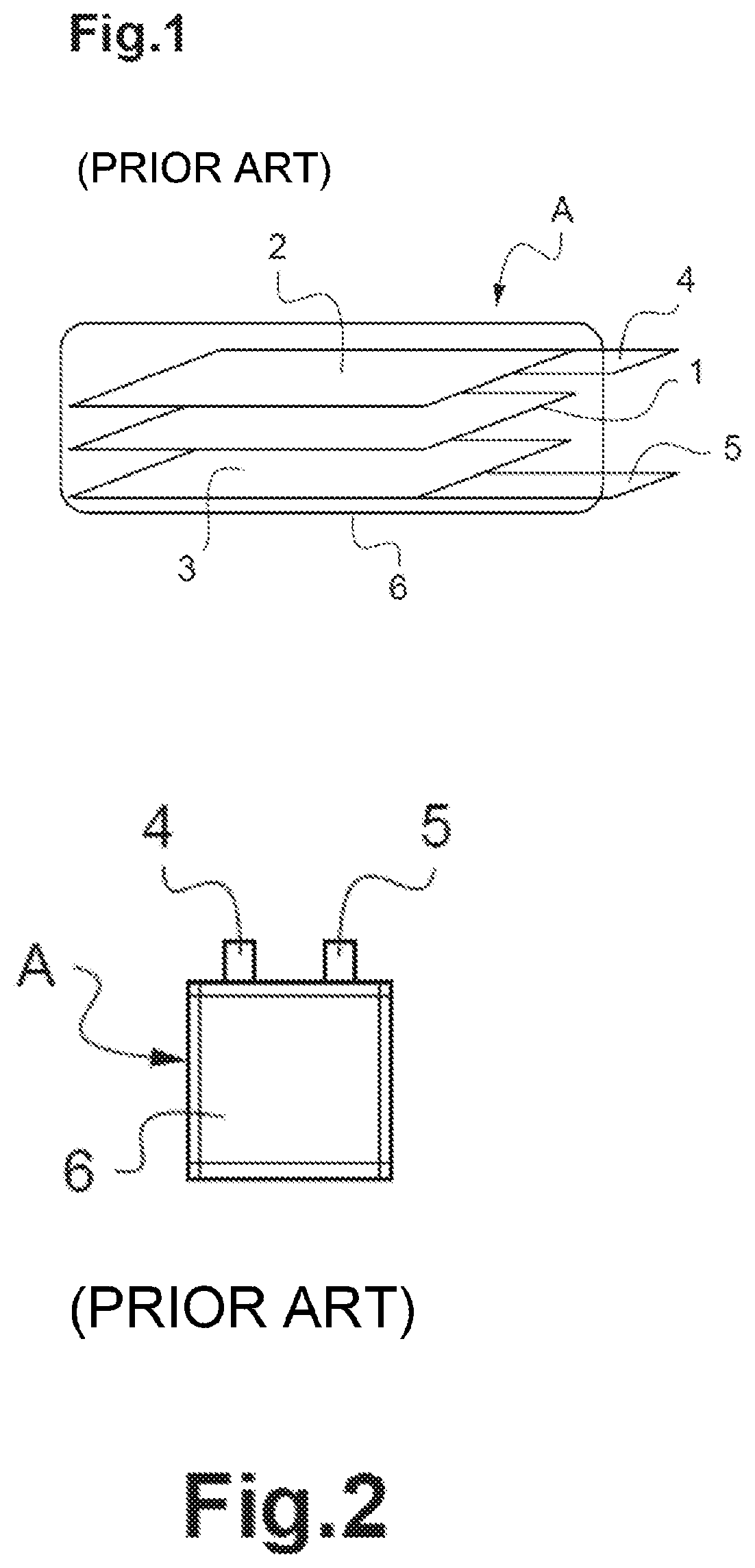
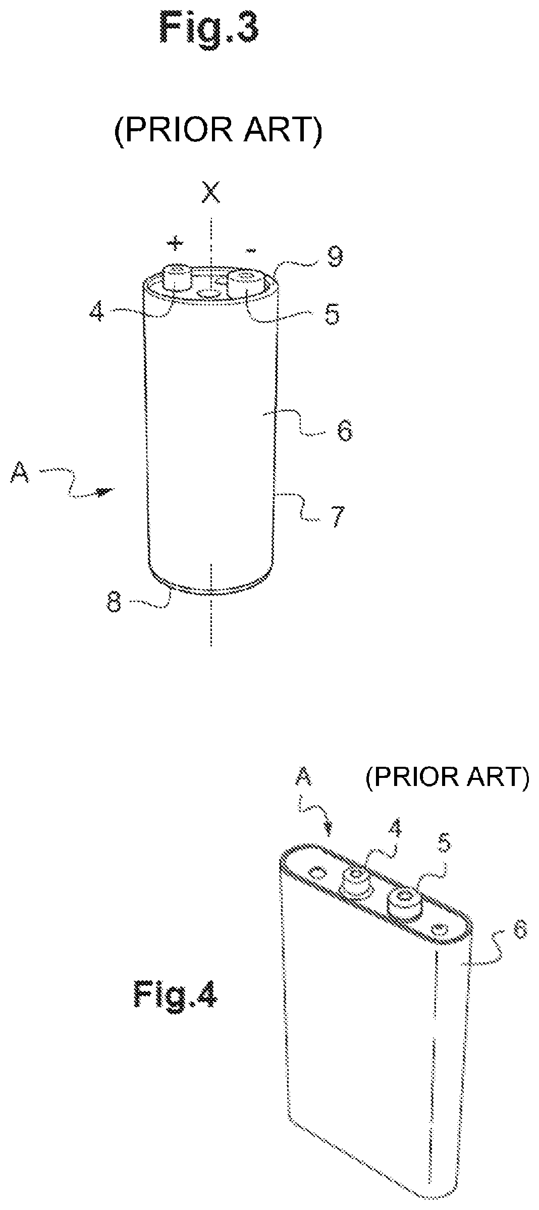
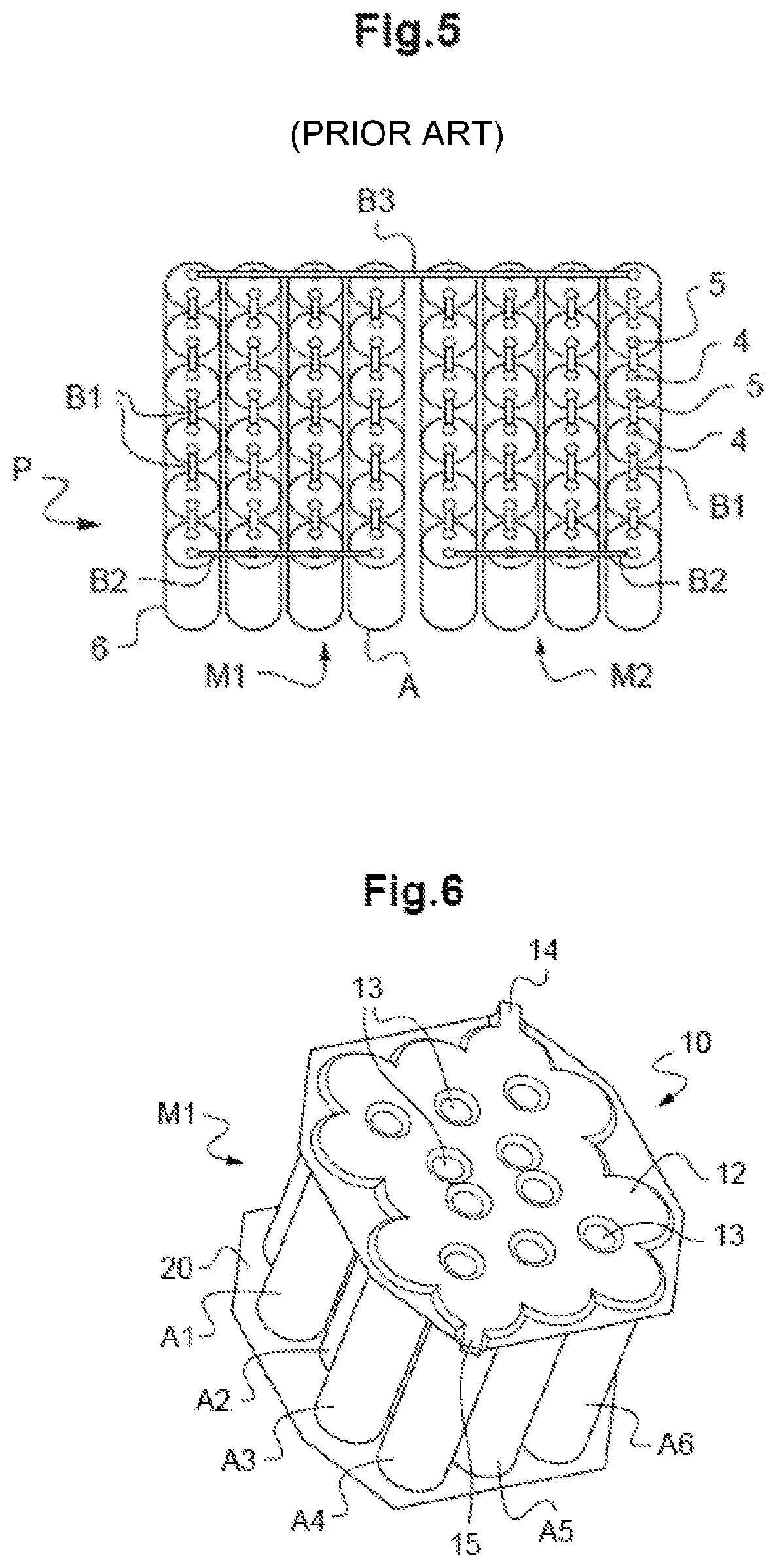
[0133]FIGS. 1 to 5 relate to different examples of Li-ion accumulator batteries, flexible packagings and accumulator battery housings and a battery pack according to the prior art. These FIGS. 1 to 5 have already been commented on in the preamble and are therefore not commented on any more below.

[0134]For the sake of clarity, the same references denoting the same elements according to the prior art and according to the invention are used for all of FIGS. 1 to 9.

[0135]Throughout the present application, the terms “lower”, “upper”, “bottom”, “top”, “below” and “above” should be understood with reference to Li-ion accumulator battery housings that are inclined with respect to the vertical, that is to say with a busbar according to the invention inclined with respect to the horizontal.

[0136]FIGS. 6 and 6A show a first example of a busbar 10 according to the invention in a module M1 of a battery pack P of Li-ion accumulator batteries, A1, A2, . . . , A17. In the illustrated examples, the...


PUM

PropertyMeasurementUnit
voltageaaaaaaaaaa
pressuresaaaaaaaaaa
temperatureaaaaaaaaaa

Abstract

A busbar for a battery pack, intended to electrically connect at least one electrochemical accumulator battery of the pack, preferably to electrically connect several electrochemical accumulator batteries of the pack to one another, including an electrically conductive and sealtight envelope itself intended to channel the current of the accumulator batteries and designed to contain a heat transfer liquid whose vaporization temperature is chosen so as to be between a value close to 90% of the self-heating temperature and a value close to 110% of the thermal runaway temperature of the accumulator batteries of the pack, the sealtight envelope being designed to guarantee an injection of heat transfer liquid as close as possible to each accumulator battery to which it is intended to be connected, preferably close to at least one of its output terminals.

Description

TECHNICAL FIELD[0001]The present invention relates to the field of electrochemical accumulator batteries, and more particularly to metal-ion accumulator batteries.[0002]The invention relates more particularly to a busbar for a battery pack.[0003]It is recalled here that a busbar is a strip or bar made of electrically conductive material, possibly laminated with one or more electrically insulating materials, and that is fastened, preferably screwed or welded, to an output terminal of at least one electrochemical accumulator battery in order to create the electrical connection to another electrochemical accumulator battery of a battery pack or another electrical input / output element.[0004]The invention aims primarily to optimize the cooling of the accumulator batteries of a battery pack, such that the energy of a thermal runaway of a given accumulator battery within the pack is not able to propagate to the other accumulator batteries.[0005]Although it is described with reference to a ...

Claims


Application Information

Patent Timeline
Patent Type & Authority Patents(United States)
IPC IPC(8): H01M50/529H01M10/6568H01M10/6569H01M50/543H01M4/38H01M4/505H01M4/525H01M4/583H01M10/0525H01M4/02H01M50/213H01M50/271H01M50/503H01M50/505H01M50/516H01M50/524H01M50/548H01M50/559H01M50/566
CPCH01M50/529H01M4/382H01M4/505H01M4/525H01M4/583H01M10/0525H01M10/6568H01M10/6569H01M50/543H01M2004/027H01M2004/028H01M10/6556H01M2220/20H01M10/625H01M10/627H01M10/643H01M10/613H01M10/6551H01M10/6553H01M10/656H01M2220/10Y02E60/10H01M50/559H01M50/213H01M50/516H01M50/503H01M50/566H01M50/548H01M50/524H01M50/505H01M50/271
Inventor MASSON, OLIVIERCOSTE, PIERREREYTIER, MAGALI
Owner COMMISSARIAT A LENERGIE ATOMIQUE ET AUX ENERGIES ALTERNATIVES
Why Eureka
Try Eureka