Device for filtering liquid drawn in between two superimposed layers of filtering media

Active Publication Date: 2021-05-06
VITESCO TECH GMBH
View PDF0 Cites 0 Cited by
  • Summary
  • Abstract
  • Description
  • Claims
  • Application Information

AI Technical Summary

Benefits of technology

[0018]In the case of such a tank, the outlet orifice is preferably produced on a wall that is at least partially grooved, and the filtration device is positioned facing a grooved part of said wall. In this way, the liquid from the tank can always access both faces of the filtration device. Furthermore, the grooving encourages exchanges of heat be

Problems solved by technology

This is because certain impurities are liable to foul

Method used


Image

  • Device for filtering liquid drawn in between two superimposed layers of filtering media
  • Device for filtering liquid drawn in between two superimposed layers of filtering media

Examples


Embodiment Construction

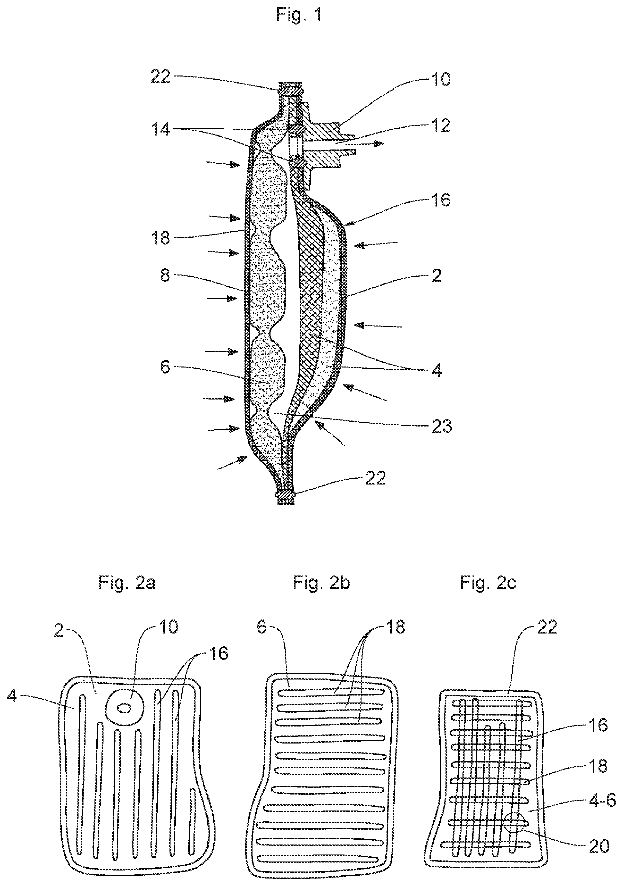
[0025]In FIG. 1, the view in longitudinal section of a filtration device reveals a first exterior face 2, a first filtering layer 4, a second filtering layer 6, a second exterior face 8 and an intake connector 10.

[0026]The filtration device illustrated here is intended for example to sit in an additive tank in a motor vehicle. More specifically, it is for example a filter for a solution of urea, known by the designation AUS32 or else by the registered trade name ADBLUE. The intake connector 10 of the filtration device may therefore be mounted on the outlet orifice of this tank in such a way that all the liquid leaving the tank passes through said filtration device.

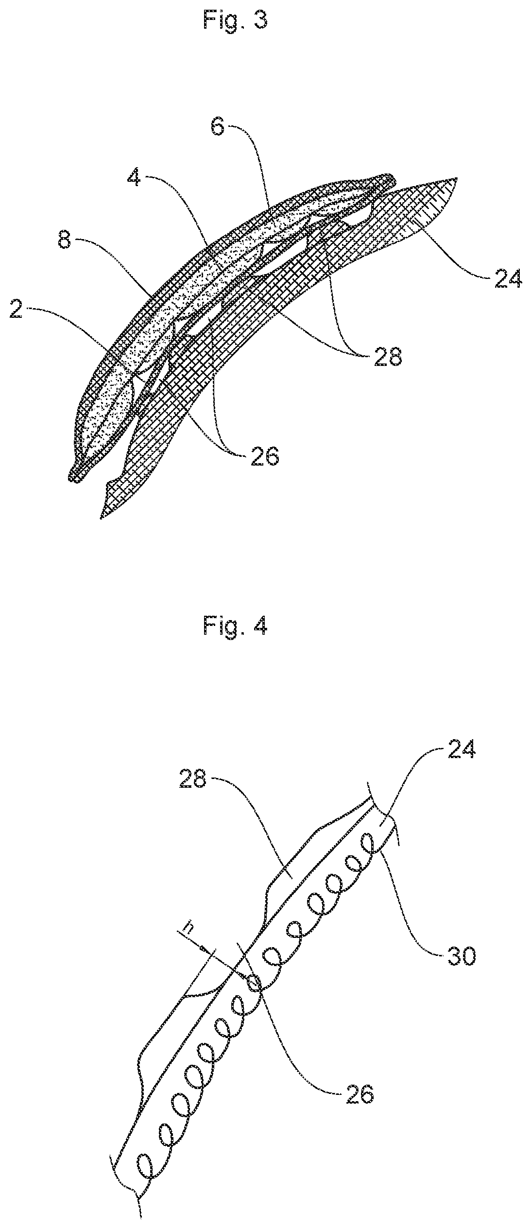
[0027]In a novel manner, the filtration device proposed here is produced in the form of a stack of four filtering layers welded together around their periphery.

[0028]In general, in the present description, the welds may be produced for example by ultrasonic welding, using the width of a sonotrode-anvil assembly to define t...


PUM

PropertyMeasurementUnit
Permeabilityaaaaaaaaaa

Abstract

Disclosed is a filtration device for a liquid, including: at least two superimposed layers of filter media having weld lines creating strips between them, the layers of filter media having weld lines being superimposed such that the weld lines of one layer form, with the weld lines of the other layer, a mesh structure when viewed at an angle normal to the layers of filter media; a first external face and a second external face each being produced at least locally from a water-permeable material, the layers of filter media being positioned between the external faces; and an intake connector used for drawing liquid in through the filtration device.

Description

BACKGROUND OF THE INVENTIONField of the Invention[0001]The present invention relates to a filtration device for a liquid. This device is more particularly intended for purifying an additive used in an internal combustion engine for limiting the pollutant emissions of this engine.Description of the Related Art[0002]For around twenty years, certain vehicles propelled by an internal combustion engine have been equipped with a tank intended to be filled with a solution containing urea. The solution used is known by the reference AUS32. It is an aqueous solution of urea in a 32.5% dilution. This urea, converted to ammonia, is then used in a catalytic converter to perform dive catalytic reduction (known by its English abbreviation SCR). The ammonia then makes it possible to reduce components of the NOx type present in the exhaust gases into nitrogen and water.[0003]Before being used, the solution of AUS32 type needs to be filtered to ensure that it does not contain impurities which might ...

Claims


Application Information

Patent Timeline
IPC IPC(8): B01D35/027B01D35/18B01D29/54
CPCB01D35/0273F01N3/2066B01D29/54B01D35/18B01D29/111B01D29/58F01N2610/02F01N2610/1406F01N2610/1426
Inventor MAGUIN, GEORGES
Owner VITESCO TECH GMBH
Why Eureka
Try Eureka