
Fin, method of fabricating the same and heat exchanger tube, heat exchanger and gas cooling apparatus

A heat exchanger tube and cooled technology, applied in the fields of fins, manufacturing, heat exchanger tubes, heat exchangers and gas cooling devices, can solve the problems of deterioration of durability, reduction of charging efficiency, increase of fuel cost, etc., to achieve Good cooling efficiency, effect of promoting heat exchange

Inactive Publication Date: 2006-04-05
USUI KOKUSAI SANGYO KAISHA LTD
View PDF3 Cites 29 Cited by
  • Summary
  • Abstract
  • Description
  • Claims
  • Application Information

AI Technical Summary

Problems solved by technology

[0003] However, when the temperature of EGR gas increases and the amount of EGR gas increases, its thermal process deteriorates the durability of the EGR valve, which makes people pay attention to the destruction of the EGR valve at an early stage, and thus finds a phenomenon that is due to the suction The reduction of charging efficiency caused by the increase of temperature will increase the fuel cost, so it is necessary to provide a cooling system and construct a water-cooled structure to prevent this phenomenon from happening

Method used


Image

  • Fin, method of fabricating the same and heat exchanger tube, heat exchanger and gas cooling apparatus
  • Fin, method of fabricating the same and heat exchanger tube, heat exchanger and gas cooling apparatus
  • Fin, method of fabricating the same and heat exchanger tube, heat exchanger and gas cooling apparatus

Examples


Embodiment 1

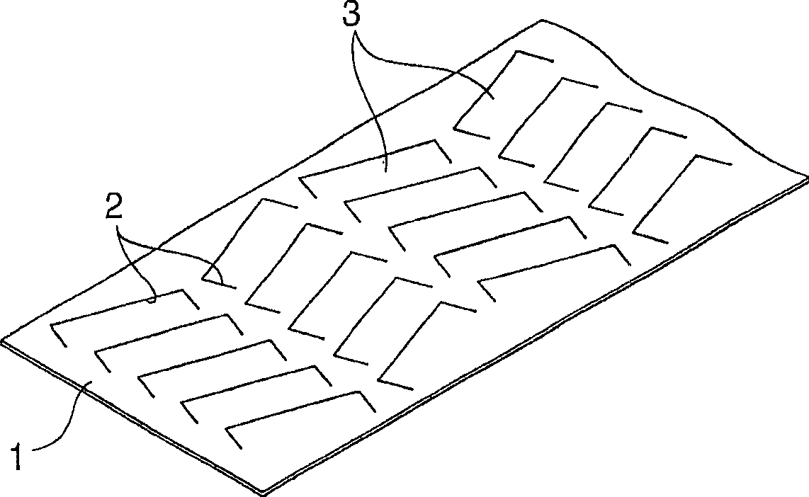
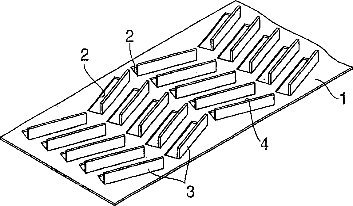
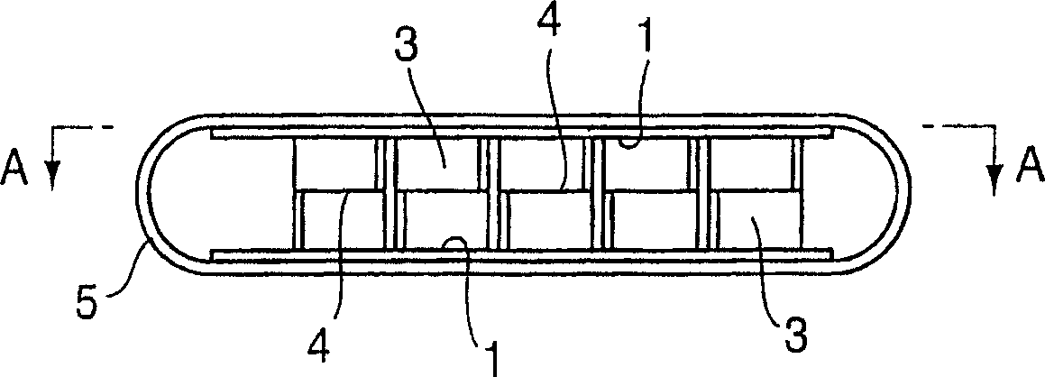
[0046] As shown in FIG. 1, according to the plate fin 3 for agitating fluid according to the first embodiment of the present invention, a thin plate made of austenitic stainless steel SUS304, SUS316 or the like and having a thickness of about 0.1 to 0.5 mm is made into a predetermined size. Rectangular shape to provide excavation material, pressing two sheets of sheet material to form a plurality of cutouts 2 similar to grooves and having a predetermined size, the direction of the cutouts can be as follows Figure 1A The alternation shown is different. Next, cut the notched portion of the remaining cut-out portion 2 and erect it perpendicular to the surface of the plate, thus forming a plate 1 with a fluid-stirring plate fin 3 oriented in its respective Alternately different on the rows, the blade edge 4 of the plate fin consists of linear lines inclined to the longitudinal direction. Thereafter, by preparing two supplied plates 1 and butting the blade edges 4 of the plate fi...

Embodiment 2

[0049] attached Figure 5B The illustrated fluid agitating plate fin 3 is similar to that of Example 1, except that the plate is constructed by joining the two plates of Example 1 longitudinally, on the left and right plates bordering the middle fold 1a-3 provided with a predetermined cutout portion, Figure 5A The shown plate fin 3a for agitating the fluid is formed by erecting the remaining notch portion of the outer cutout, after which the plate is folded at the middle fold 1a-3, and the plate 1 (1a-1) Butt with the respective blade edges 4a of the plate fins 3a formed on the plate 2 (1a-2) to stir the fluid, so that they are opposite to each other, similar to Embodiment 1, thus completing a heat exchanger with the plate fins 3a built in Tubes Similar to Example 1, this heat exchanger tube was subjected to a cooling test by an EGR gas cooling device (shell-and-tube heat exchanger), and as a result, this Example could obtain the same cooling efficiency as Example 1.

Embodiment 3

[0051] A fluid-stirring plate fin 3b similar to that of Embodiment 1 is provided, except that the shape of the fluid-stirring plate fin formed on the plate is to replace the fluid-stirring of Embodiment 1 or Embodiment 2 by bending the blade edge 4a in the longitudinal direction. The plate fins 3 and 3a are obtained when by using the fins 3b to compose the heat exchanger tubes of the plate fins 3b with the agitation fluid built in, and setting the heat exchanger tubes to the EGR gas cooling device to receive cooling similar to Example 1 During the test, by comparing with Example 1, it can be determined that the cooling efficiency is further improved.


PUM


Abstract

The invention relates to a shell and tube heat exchanger used as a coolant mechanism. The shell and tube heat exchanger comprises a plate-fin arranged inside or outside a heat exchanger tube, and at least one heat exchanger tube internally provided with the plate-fin. Through the heat exchanger has simple structure and easy manufacture, the heat exchanger can still limberly process fluid bodies with different shapes, promote the effective heat exchanging action of the fluid bodies, obtain good cooling efficiency, and can process a plurality of fluid bodies. The plate-fin that the invention relates to is the plate-fin for stirring liquid; the plate-fin is arranged inside or outside the heat exchanger tube to lead the fluid bodies which is composed of cooled medium or refrigeration medium to flow inside or outside the heat exchanger tube, thus impingiment flow or vortex flow with stirring action are generated; the plate-fin is arranged inside or outside the heat exchanger tube, and thus the blade edges of the plate-fin are butted and jointed up and down to enable the blade edges opposite to each other, and each butted and jointed blade edges are crossed with each other. The invention also relates to a method for manufacturing the plate-fin as well as the heat exchanger tube internally provided with the plate-fin, and the heat exchanger or an EGR gas cooling device provided with at least one heat exchanger tube.

Description

technical field [0001] The present invention relates to a fin structure for agitating fluid in a heat exchanger, in particular to a plate fin for agitating fluid arranged on the inside or outside of a heat exchanger tube of a heat exchange cooling device. Composed of refrigerant medium, turbulence or vortex with stirring effect is generated in the fluid flowing inside or outside the heat exchanger tube, including the cooled medium or the refrigerant medium, which increases the distance between the wall surface of the heat exchanger tube and the fluid contact to obtain a significant heat exchange effect, the invention relates to a method of manufacturing plate fins and heat exchanger tubes with built-in plate fins, and heat exchangers or gas cooling devices of the heat exchange type having at least one heat exchanger tube . Background technique [0002] In recent years, starting from the EGR cooler for recirculating automobile exhaust gas, different modes of fluid heat excha...

Claims


Application Information

Patent Timeline
Patent Type & Authority Applications(China)
IPC IPC(8): F28F9/24F28F1/40F28F1/10
CPCF02M25/0737F28F13/12F28D21/0003Y02T10/121F28F1/40F28D7/1684F28F3/02F02M26/32
Inventor 桥本康明后藤忠弘
Owner USUI KOKUSAI SANGYO KAISHA LTD
Learn More