
Evaporation Cycle Heat Exchange System for Vehicle

a heat exchange system and evaporation cycle technology, applied in the field of evaporation cycle heat exchange systems for vehicles, can solve the problems of reducing engine efficiency, reducing engine power, and reducing engine durability, so as to improve the cooling efficiency of the entire cooling system, reduce the size of components, and easy to evaporate

Active Publication Date: 2010-05-27
HYUNDAI MOTOR CO LTD
View PDF2 Cites 30 Cited by
  • Summary
  • Abstract
  • Description
  • Claims
  • Application Information

AI Technical Summary

Benefits of technology

[0044]The present invention has been made in an effort to solve the above-described problems associated with the prior systems. Accordingly, the present invention provides a new type of evaporation cycle heat exchange system for a vehicle, in which an evaporative heat exchanger using the principle that a working fluid is easily evaporated as its boiling point is lowered at low pressure and the evaporated fluid is moved by a pressure difference caused by volume expansion and capillary phenomenon is employed to cool coolant circulating through a vehicle cooling system. Accordingly, it is possible to improve the cooling efficiency of the entire cooling system, reduce the size of components to comply with pedestrian protection regulations, improve fuel efficiency, and ensure the stability of the system.
[0045]Moreover, the present invention provides an evaporation cycle heat exchange system for a vehicle, in which a product-integrated or line-integrated evaporative heat exchanger capable of being mounted in various vehicle components such as an inverter, a fuel cell stack, an oil fan of an internal combustion engine, a turbocharger, an automatic transmission oil fan, etc. is employed. Accordingly, it is possible to easily apply the evaporative heat exchanger to various vehicle components and various vehicle models, and thus it is possible to increase the degree of freedom of the design of the cooling system.
[0046]In one aspect, the present invention provides an evaporation cycle heat exchange system for a vehicle, the system including an evaporative heat exchanger including an evaporative heat exchange unit, a condensing heat exchange unit, and a pipe line provided between both the heat exchange units to circulate a working fluid and performing heat exchange in such a manner that the working fluid is easily evaporated as its boiling point is lowered at low pressure and the working fluid at one side is moved to the other side by a pressure difference caused by volume expansion and capillary phenomenon.

Problems solved by technology

When the temperature of the components excessively increases, the strength of the components is decreased to cause engine trouble, the durability of the engine is reduced, and the combustion conditions of the engine become worse, thus reducing the engine's power.
Moreover, when the engine is over-cooled, the amount of heat lost by the cooling is large, and thus the efficiency of the engine is reduced and the amount of fuel used is increased.
Since the cooling systems of most vehicles employ the radiator, which transfers heat from the coolant to the air, it is difficult to improve the cooling efficiency, and the size or capacity of the radiator is increased.
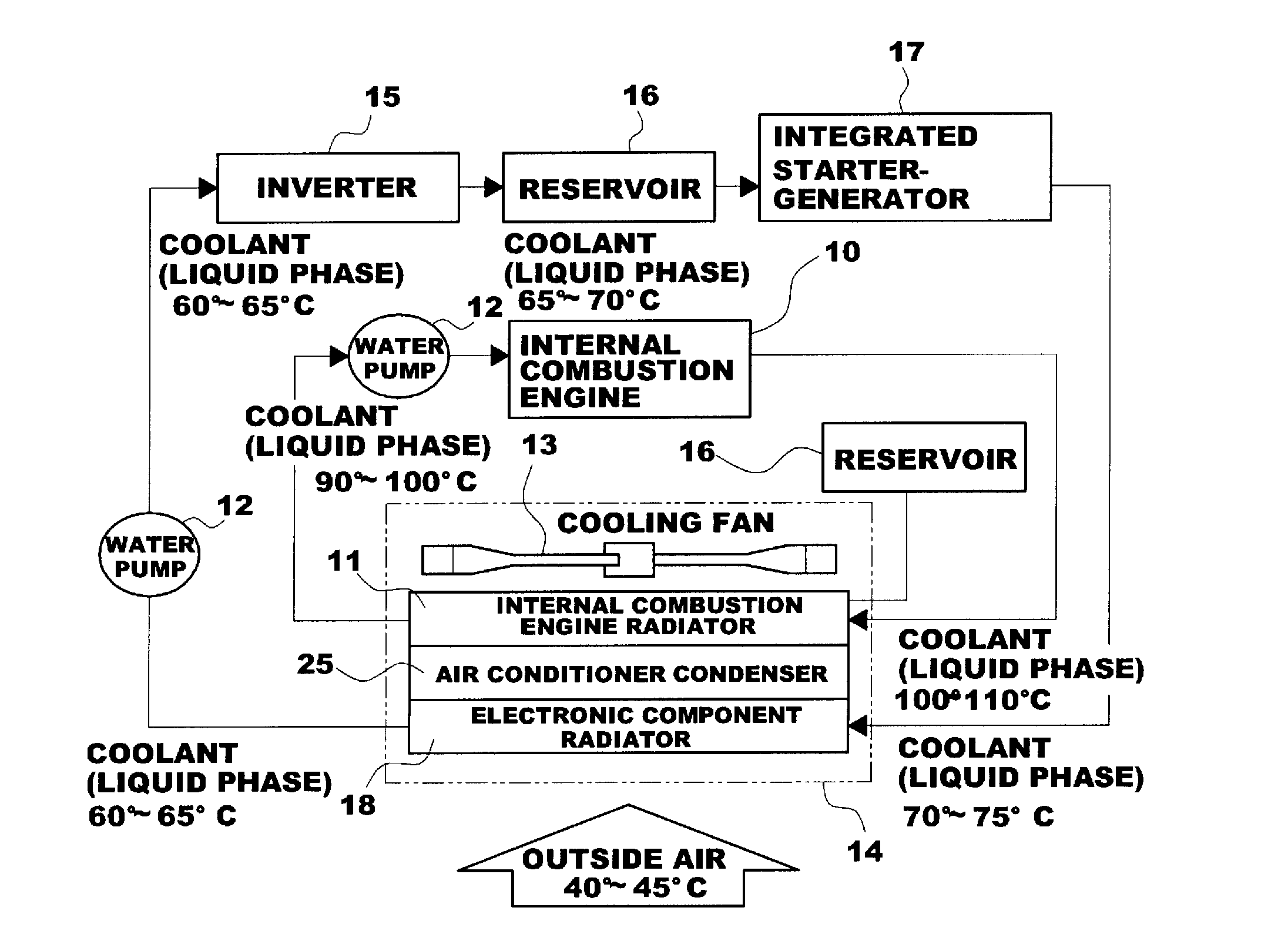
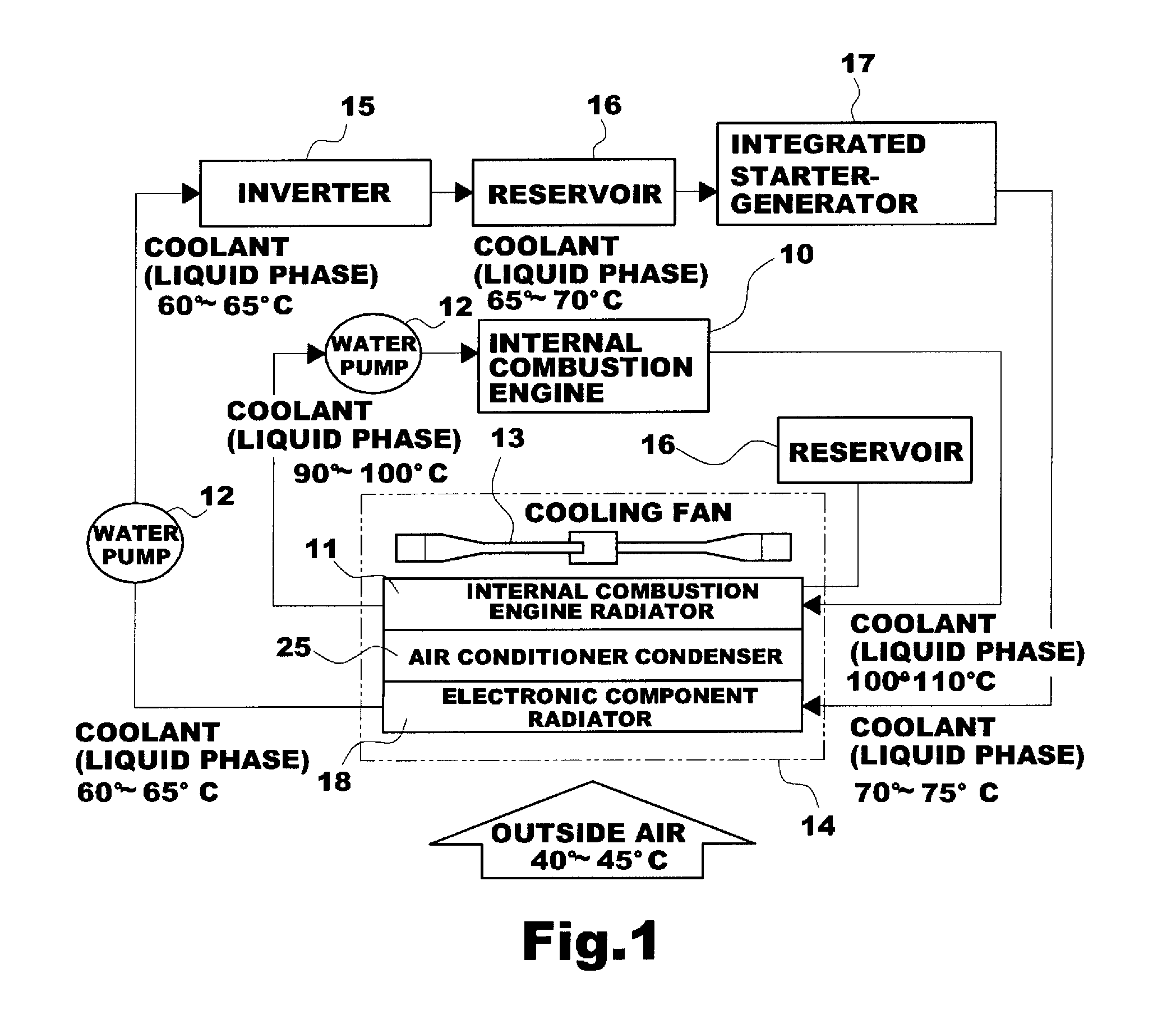
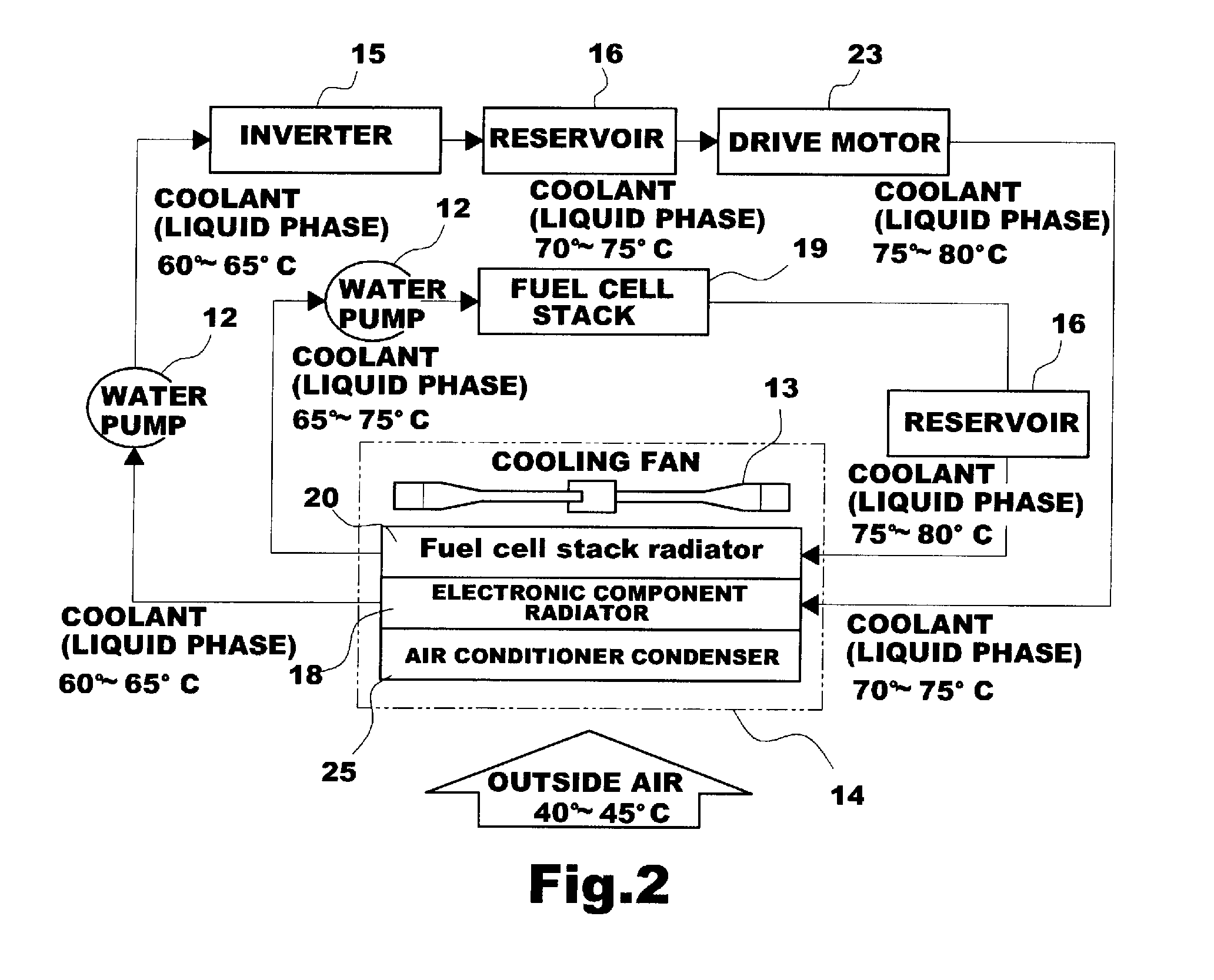
However, in the case of the electronic component radiator, the temperature at an inlet side ranges from 60 to 65° C. and the temperature of outside air ranges from 40 to 45° C., and thus the temperature difference between two fluids is 15 to 25° C., which causes deterioration of the cooling efficiency.
However, in the case where the electronic component radiator and an air conditioner condenser are positioned in front of the fuel cell stack radiator, it is difficult to improve the cooling efficiency.
However, it is impossible to reduce the thickness of the conventional radiator due to the structures of the header and tank, and if the size of the cooling module is reduced, it is difficult to ensure the cooling efficiency.
Moreover, a turbocharger intercooler radiator has the same problem as the internal combustion engine.
When the automatic transmission oil is over-cooled, the oil viscosity is increased, and thus a larger drive force is required, which is very disadvantageous in view of fuel efficiency.

Method used


Image

  • Evaporation Cycle Heat Exchange System for Vehicle
  • Evaporation Cycle Heat Exchange System for Vehicle
  • Evaporation Cycle Heat Exchange System for Vehicle

Examples


Embodiment Construction

[0072]Reference will now be made in detail to various embodiments of the present invention(s), examples of which are illustrated in the accompanying drawings and described below. While the invention(s) will be described in conjunction with exemplary embodiments, it will be understood that present description is not intended to limit the invention(s) to those exemplary embodiments. On the contrary, the invention(s) is / are intended to cover not only the exemplary embodiments, but also various alternatives, modifications, equivalents and other embodiments, which may be included within the spirit and scope of the invention as defined by the appended claims.

[0073]FIG. 5 is a schematic diagram showing an evaporative heat exchanger employed in an evaporation cycle heat exchange system for a vehicle in accordance with various embodiments of the present invention.

[0074]As shown in FIG. 5, the evaporative heat exchanger 100 has a structure in which a pipe line 130 connects an evaporative heat...


PUM


Abstract

An evaporation cycle heat exchange system for a vehicle is provided. The evaporation cycle heat exchange system is a new type of cooling system that cools vehicle electronic components, a fuel cell stack, an internal combustion engine, an automatic transmission, a turbocharger, etc. using an evaporative heat exchanger, thus improving cooling efficiency and reducing the size of components such as a radiator. The evaporation cycle heat exchange system cools coolant circulating through a vehicle cooling system by employing an evaporative heat exchanger in which a working fluid flows by a pressure difference caused by volume expansion and capillary phenomenon. Accordingly, it is possible to improve the cooling efficiency of the entire cooling system, reduce the size of components to comply with pedestrian protection regulations, improve fuel efficiency, and ensure the stability of the system. Moreover, the present invention provides an evaporation cycle heat exchange system for a vehicle, in which a product-integrated or line-integrated evaporative heat exchanger capable of being mounted in various vehicle components such as an inverter, a fuel cell stack, an oil fan of an internal combustion engine, a turbocharger, an automatic transmission oil fan, etc. is employed. Accordingly, it is possible to easily apply the evaporative heat exchanger to various vehicle components and various vehicle models, and thus it is possible to increase the degree of freedom of the design of the cooling system.

Description

CROSS-REFERENCE TO RELATED APPLICATION[0001]The present application claims priority of Korean Patent Application Number 10-2008-0118278 filed Nov. 26, 2008, the entire contents of which application is incorporated herein for all purposes by this reference.BACKGROUND OF THE INVENTION[0002]1. Field of the Invention[0003]The present disclosure relates to an evaporation cycle heat exchange system for a vehicle. More particularly, it relates to an evaporation cycle heat exchange system for a vehicle, which is a new type of cooling system that cools vehicle electronic components, a fuel cell stack, an internal combustion engine, an automatic transmission, a turbocharger, etc. using an evaporative heat exchanger, thus improving cooling efficiency and reducing the size of components such as a radiator.[0004]2. Description of Related Art[0005]The temperature of combustion gas in a cylinder of an internal combustion engine typically ranges from 2,000 to 2,500° C., and most of the heat from th...

Claims


Application Information

Patent Timeline
IPC IPC(8): F01P9/02F28D15/04
CPCB60K6/32B60Y2400/435B60K2001/003B60K2001/005F01P9/06F28D15/0266F28D15/043F28D2021/0043H01M8/04029H01M8/04074H01M2250/20Y02E60/50Y02T10/6226Y02T90/32Y02T90/34B60H1/00271B60H1/3202B60K6/485Y02T10/62Y02T90/40F01P3/22F01P3/18F01P3/12
Inventor KIM, JAE YEON
Owner HYUNDAI MOTOR CO LTD
Learn More