Heat pump and structure of extraction heat exchanger thereof

a heat exchanger and heat pump technology, applied in the field of heat pumps, can solve the problems of high cost, complex structure, and difficulty in operation of heat pumps, and achieve the effect of reducing the quantity of generated flash gas of refrigerant entering the evaporator

Inactive Publication Date: 2006-05-25
DAEWOO ELECTRONICS CO LTD
View PDF3 Cites 20 Cited by
  • Summary
  • Abstract
  • Description
  • Claims
  • Application Information

AI Technical Summary

Benefits of technology

[0015] According to the heat pump equipped with an extraction heat exchanger of the present invention, in order to guaranteeing a heat source in cold climates like the Achilles' tendon, a part of the super-cooled liquid refrigerant (about 20% to 35% intrinsic mass) is extracted. At that time, the quantity of the extracted refrigerant is adjusted according to low temperature conditions (outdoor air temperature) using the extraction electronic expansion valve to evaporate the supercooled liquid refrigerant in the extraction heat exchanger. The extracted refrigerant is transmitted to the accumulator disposed in front of the compressor, and the rest of the super-cooled liquid refrigerant undergoes heat exchange between the rest of the supercooled liquid refrigerant and the extracted refrigerant so that the refrigerant is further super-cooled and decompressed. The refrigerant is expanded in the main electronic expansion valve and enters an outdoor unit (evaporator). The refrigerant is evaporated in the outdoor unit and is mixed with the extracted refrigerant at the inlet of the accumulator so that the quantity of obtained heat by the evaporator in the heating mode can be reduced by 20% to 35%. Super-cooling is developed so that the quantity of generated flash gas of refrigerant entering the evaporator can be reduced.

Problems solved by technology

Since, according to the conventional art, it is very difficult to guarantee a heat source at a low-temperature side in cold climates, it is difficult to operate the heat pump due to driving loss caused by a high compression ratio and frosting, and an increase in dryness caused by the flashing of refrigerant.
However, since the above methods have disadvantages of high costs and complex structure, recently, inverters and electronic expansion valves are employed to precisely adjust superheat imbalances and to increase capacity.
Moreover, although, in the case of employing the inverter, insufficient heat obtained from the low temperature heat source, i.e. short heating capacity is supplemented by increasing the frequency of the inverter in the heating mode, system efficiency is decreased.
In addition, in the heating mode, in the case of supplementing the insufficient heat via the electric heater and the overload operation by the inverter, the efficiency is decreased and a capacity changing device such as the inverter is employed so that manufacturing costs are increased.
Moreover, in a conventional economizer, due to inconsistent capacity adjustment, there is the risk of vapor induction and that the superheat unbalance exceeds a predetermined valve so that the compressor may catch fire.
In particular, in a two-stage compression cycle, although two compressors are employed, or one compressor is non-conventionally machined so that the extracted refrigerant undergoes heat exchange and is injected into an intermediate pressure zone between a high pressure zone and a low pressure zone, the mass production of the non-conventional machining compressor cannot be achieved due to the non-conventional machining.
Moreover, since, due to tubules, the distribution of the flow rate is not uniform, and generally precise control is very difficult when a solenoid valve is used, it is difficult to maintain uniform operation.

Method used


Image

  • Heat pump and structure of extraction heat exchanger thereof
  • Heat pump and structure of extraction heat exchanger thereof
  • Heat pump and structure of extraction heat exchanger thereof

Examples


Embodiment Construction

[0023] Hereinafter, the preferred embodiments of a heat pump air conditioner according to the present invention will be described in detail with reference to the accompanying drawings.

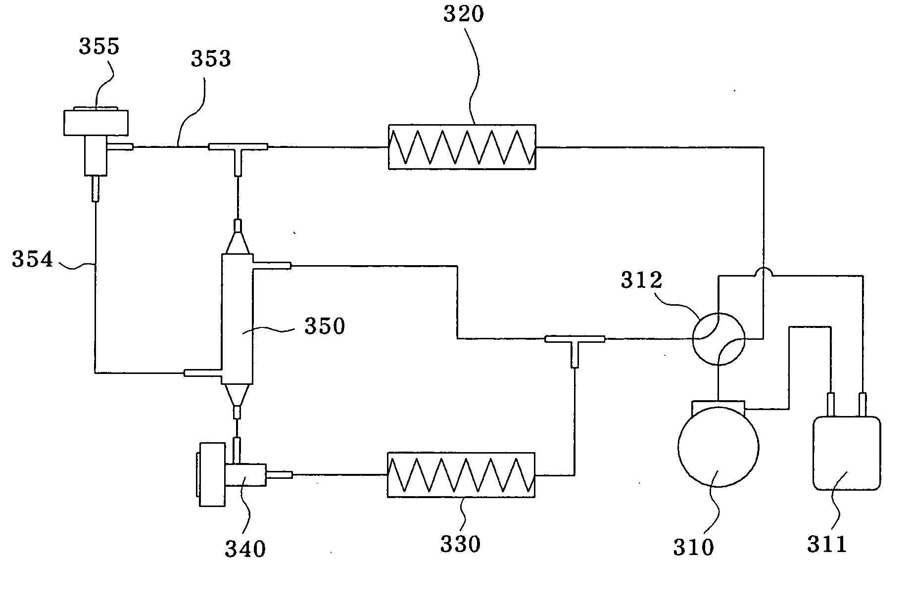
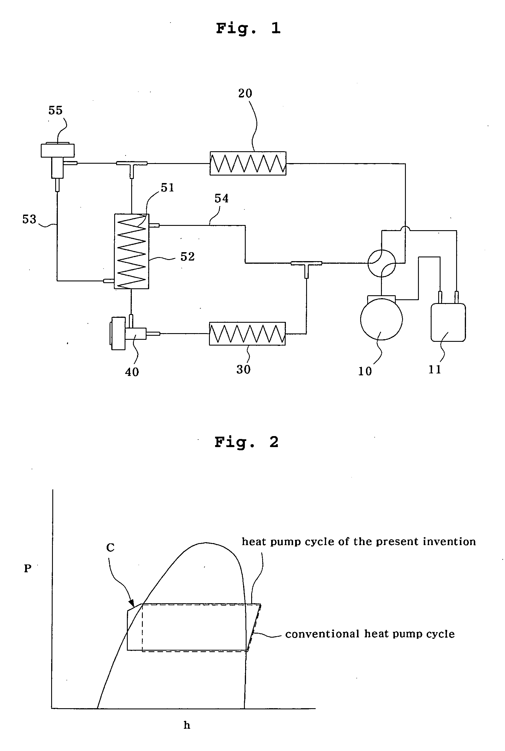
[0024]FIG. 1 is a schematic view illustrating a heat pump equipped with an extraction heat exchanger according to a first preferred embodiment of the present invention, and FIG. 2 is a schematic P-h diagram of the heat pump with an extraction heat exchanger according to the first preferred embodiment of the present invention. Here, as a preferred embodiment of the heat pump according to the present invention, a refrigerating cycle in the heating mode among cycles of the heat pump will be described.

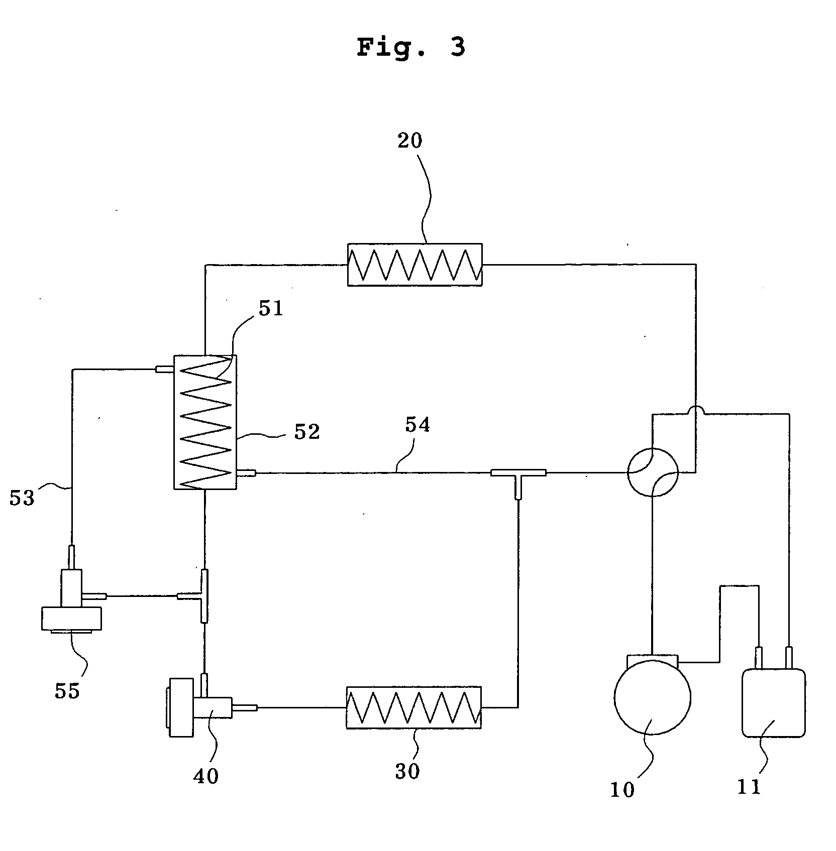
[0025] As shown in the drawing, the heat pump according to the first preferred embodiment of the present invention includes a compressor 10, a condenser 20, an evaporator 30, a main electronic expansion valve 40, and an extraction heat exchanger.

[0026] The compressor 10 sucks and compresses low-temperature...


PUM


Abstract

A heat pump equipped with an extraction heat exchanger includes a compressor sucking low-temperature-and-low-pressure liquid refrigerant, and compressing and discharging the low-temperature-and-low-pressure liquid refrigerant into high-temperature-and-high-pressure liquid refrigerant, a condenser in which air passing therethrough absorbs heat from the liquid refrigerant to liquefy the liquid refrigerant, an evaporator in which refrigerant absorbs heat from indoor air and is evaporated to cool indoor air, a main electronic expansion valve connected between the condenser and the evaporator to decompress the liquid refrigerant liquefied in the condenser such that the decompressed refrigerant is easily evaporated in the evaporator and flows at a predetermined flow rate; and the extraction heat exchanger branching a part of the high-temperature-and-high-pressure liquid refrigerant, and performing and bypassing heat exchange between high-temperature-and-high-pressure super-cooled liquid refrigerant and high-temperature-and-high-pressure refrigerant passing through a heat exchanging refrigerant tube between the condenser and the main electronic expansion valve to an accumulator.

Description

BACKGROUND OF THE INVENTION [0001] 1. Field of the Invention [0002] The present invention relates to a heat pump equipped with an extraction heat exchanger for guaranteeing operational stability and enhancing power efficiency in the cooling mode and for supplementing a heat source in the heating mode such that the coefficient of performance is enhanced and performance in cold climates is improved, using two electronic expansion valves for controlling superheating in the heating mode, for guaranteeing a low temperature heat source, for guiding any increase in evaporation efficiency, a cycle control of the extraction heat exchanger, and relates to the structure of the extraction heat exchanger capable of being applied to the heat pump by considering uniform distribution of refrigerant and pressure decrease to change the number of tubules according to an increase in capacity of the heat pump. [0003] 2. Description of the Related Art [0004] Since, according to the conventional art, it i...

Claims


Application Information

Patent Timeline
Patent Type & Authority Applications(United States)
IPC IPC(8): F25B13/00F25B41/00
CPCF25B40/02F25B2400/13F28D7/16
Inventor PARK, YOUNG SUNLEE, YUN SUKIM, SUN SIK
Owner DAEWOO ELECTRONICS CO LTD
Why Eureka
Try Eureka