Liquid substance supply device for vaporizing system, vaporizer, and vaporization performance appraisal method

a liquid substance and vaporization system technology, applied in the direction of combustible gas purification/modification, evaporator regulation/control, separation process, etc., can solve the problems of reducing the stability and consistency affecting the stability of the flow rate, and reducing the generation of residues or bubbles. , the effect of good stability and controllability of liquid substance supply

Inactive Publication Date: 2007-01-16
ULVAC INC
View PDF30 Cites 19 Cited by
  • Summary
  • Abstract
  • Description
  • Claims
  • Application Information

AI Technical Summary

Benefits of technology

[0013]A primary objective of the present invention is to provide a liquid substance supply device which suppresses the

Problems solved by technology

However, the liquid substance which is used in such a MOCVD method can easily undergo hydrolytic reactions, and there has been a danger that its nature may change due to precipitates being formed in the liquid or the like.
Such generation of precipitates can easily lead to problems with the operation of valves provided in the liquid supply lines, or the occurrence of residues within the vaporizer or blockages due to the precipitates or the like.
As a result there have been the problems that the rate of flow may become less stable and consistent, and that, if the residues form into particles which arrive at the CVD reactor, the consistency of film deposition may be deteriorated.
If a thermal type mass flow meter is used as the mass flow meter, it can easily be influenced by the ambient temperature, and accordingly it is not desirable to locate such a meter in the vicinity of the vaporizer which attains high temperatures.
As a result there is the problem that, when determining the po

Method used


Image

  • Liquid substance supply device for vaporizing system, vaporizer, and vaporization performance appraisal method
  • Liquid substance supply device for vaporizing system, vaporizer, and vaporization performance appraisal method
  • Liquid substance supply device for vaporizing system, vaporizer, and vaporization performance appraisal method

Examples


Embodiment Construction

[0081]In the following, various embodiments of the present invention will be described with reference to the appended drawings. Overall Structure of the Vaporizing system

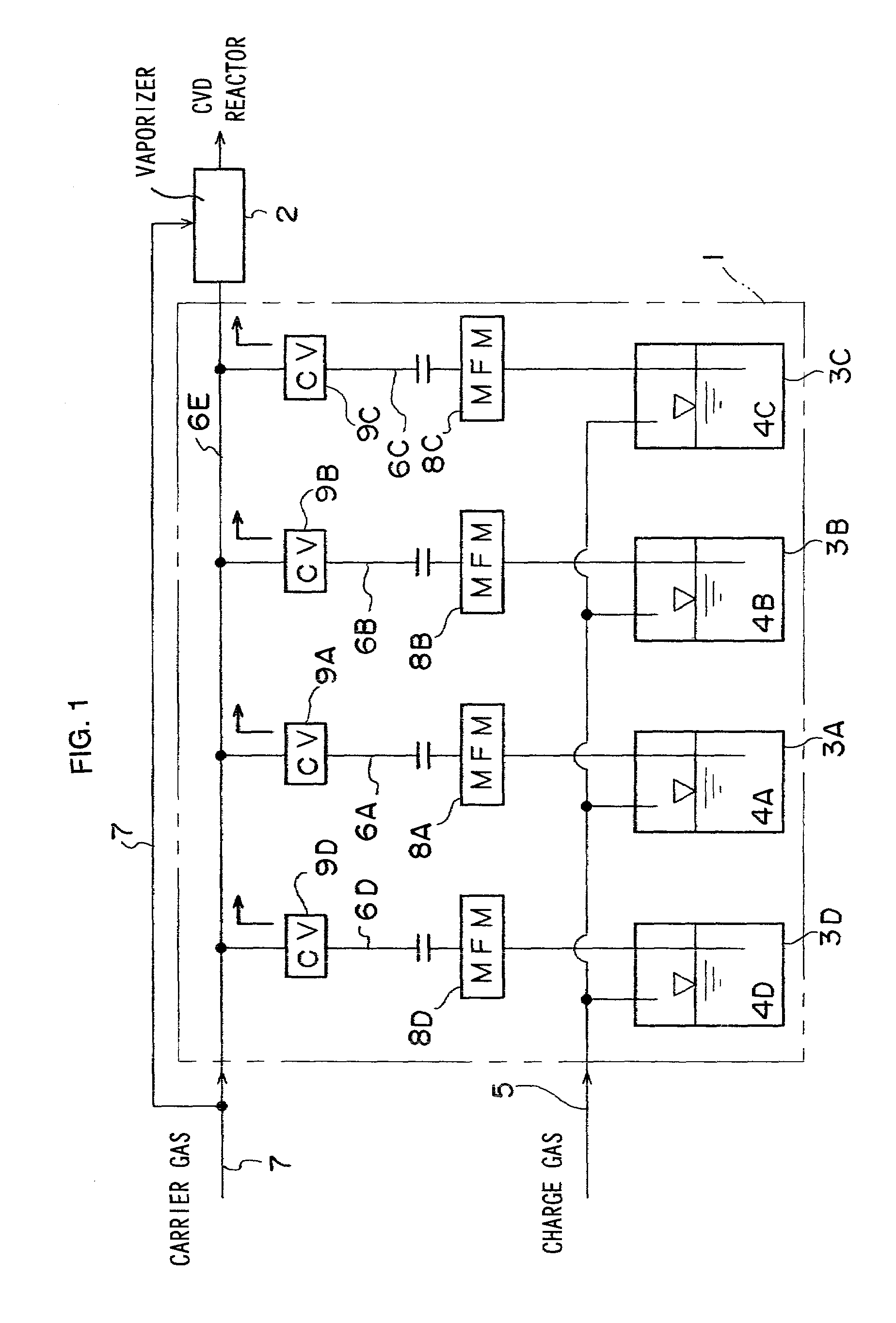
[0082]FIG. 1 is a figure showing the general structure of the vaporizing system. This liquid substance vaporizing system is comprised of a liquid substance supply device 1 and a vaporizer 2 Liquid substance which has been supplied from the liquid substance supply device 1 to the vaporizer 2, after having been vaporized in said vaporizer 2, is supplied to a CVD reactor provided in a CVD device. Various liquid substances may be used in such a MOCVD process, for example a liquid organometal such as Cu or Ta, or an organometallic solution where an organometal such as Ba, Sr, Ti, Pb, or Zr is dissolved in an organic solvent. The liquid substance may be referred to as the CVD source.

[0083]Substance containers 3A, 3B, and 3C which are provided in the liquid substance supply device 1 are charged with quantities 4A, 4B, and ...


PUM

PropertyMeasurementUnit
Fractionaaaaaaaaaa
Temperatureaaaaaaaaaa

Abstract

In a liquid substance supply device, a three port two valve directional control valve is provided in a transfer line, and a substance container and the transfer line are connected together by a four port three valve directional control valve in such a way that the four port three valve directional control valve and the substance container can be removed from the transfer line as a unit. Furthermore, in a vaporizer, an orifice member is provided to surround the end portion of an internal conduit in which flows a mixture substance consisting of a gas and a liquid substance mixed therewith, and gas for atomization is spouted into a vaporization chamber through a gap defined between the internal conduit and the orifice member. Yet further, the temperature of a vaporization surface in the vaporization chamber can be controlled independently in correspondence with the nature of the liquid substance.

Description

INCORPORATION BY REFERENCE [0001]The disclosures of the following priority applications are herein incorporated by reference:[0002]Japanese Patent Application No. 2000-292757, filed Sep. 26, 2000;[0003]Japanese Patent Application No. 2000-292758, filed Sep. 26, 2000;[0004]Japanese Patent Application No. 2000-292759, filed Sep. 26, 2000;BACKGROUND OF THE INVENTION[0005]1. Field of the Invention[0006]The present invention relates to a liquid substance supply device for a vaporizing system which vaporizes a liquid substance such as a liquid organometal or an organometal solution or the like, and also relates to a vaporizer and to a vaporization performance appraisal method.[0007]2. Description of the Related Art[0008]The MOCVD (Metal Organic Chemical Vapor Deposition) method is known as one thin film deposition method in semiconductor device manufacturing processes. In recent years this MOCVD method is rapidly coming into widespread use, since the resulting film quality and the speed o...

Claims


Application Information

Patent Timeline
IPC IPC(8): B01F3/04B01D1/00H01L21/205C23C16/448F16K11/20F16K31/122
CPCB01D1/0082C23C16/448F16K11/207F16K31/1221C23C16/4486Y10S261/65
Inventor YOSHIOKA, NAOKIKAWAMOTO, TATSUSHIKAWAO, MITSUSHIMATSUNO, SHIGERUYAMADA, AKIRAMIYASHITA, SHOJIUCHIKAWA, FUSAOKI
Owner ULVAC INC
Why Eureka
Try Eureka