Electrostatic evaporative cooling system

a technology of evaporative cooling system and turbine engine, which is applied in the direction of machines/engines, combustion air/fuel air treatment, mechanical equipment, etc., can solve the problems of evaporation of a large number of charged particles, and achieve the effect of small size and easy evaporation

Inactive Publication Date: 2005-05-03
SIEMENS ENERGY INC
View PDF17 Cites 18 Cited by
  • Summary
  • Abstract
  • Description
  • Claims
  • Application Information

AI Technical Summary

Benefits of technology

[0009]Applying an electrical charge to droplets to form charged droplets in the duct causes the droplets to repel from each other and prevents the droplets from agglomerating in the ducts. Thus, the evaporative cooling system substantially, if not completely, prevents droplets from agglomerating and settling on surfaces of the duct or other components of the evaporative cooling system. Rather, the evaporative cooling system advantageously forces the droplets to maintain their small size, which evaporate easier than larger droplets. Another advantage of this invention is that the evaporative cooling system prevents water droplets from entering the compressor and possibly damaging the blades of the compressor.

Problems solved by technology

Operating the evaporative cooling system in this manner may cause substantially all of the plurality of charged particles to evaporate before reaching the compressor.

Method used


Image

  • Electrostatic evaporative cooling system
  • Electrostatic evaporative cooling system
  • Electrostatic evaporative cooling system

Examples


Embodiment Construction

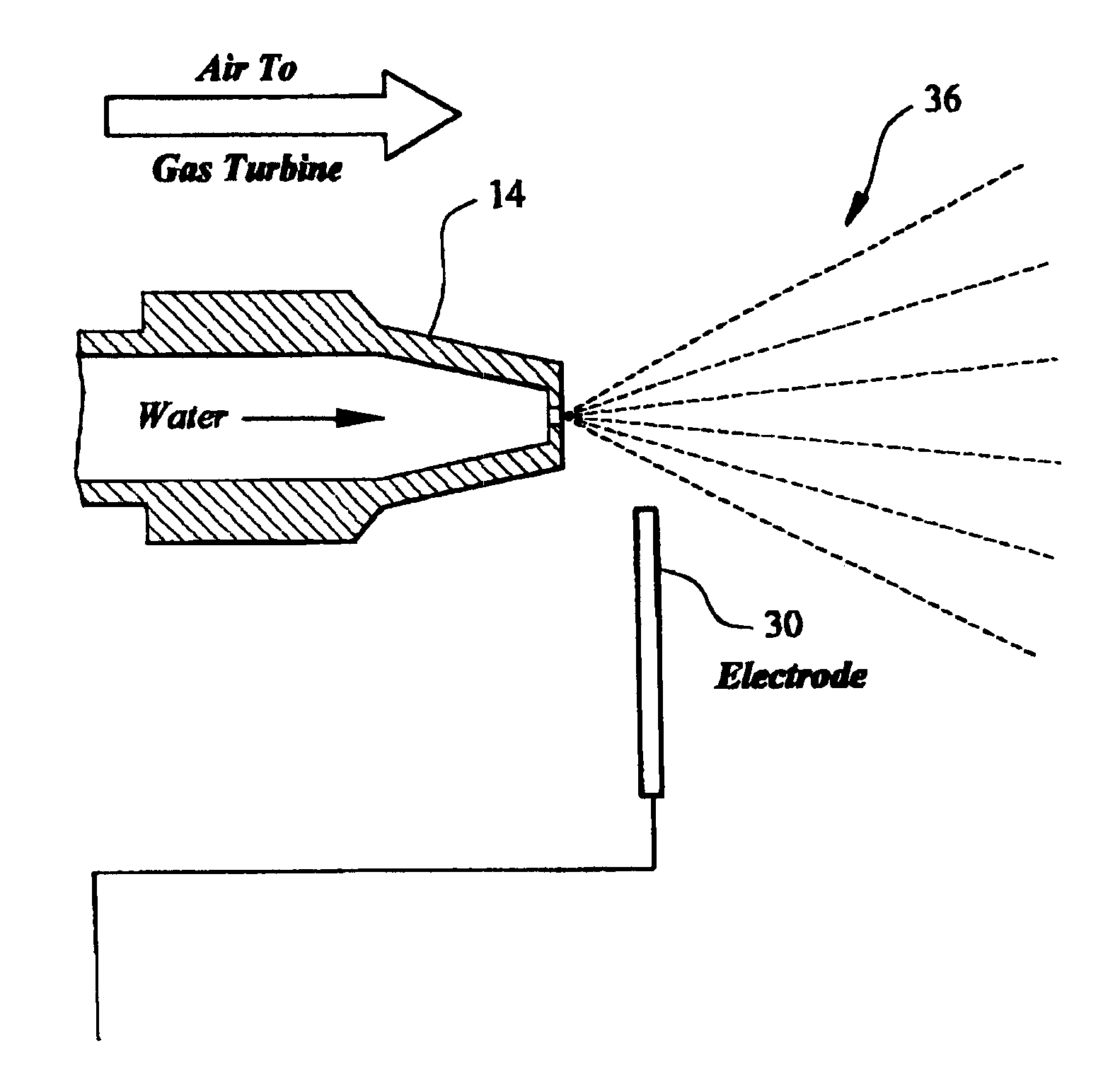
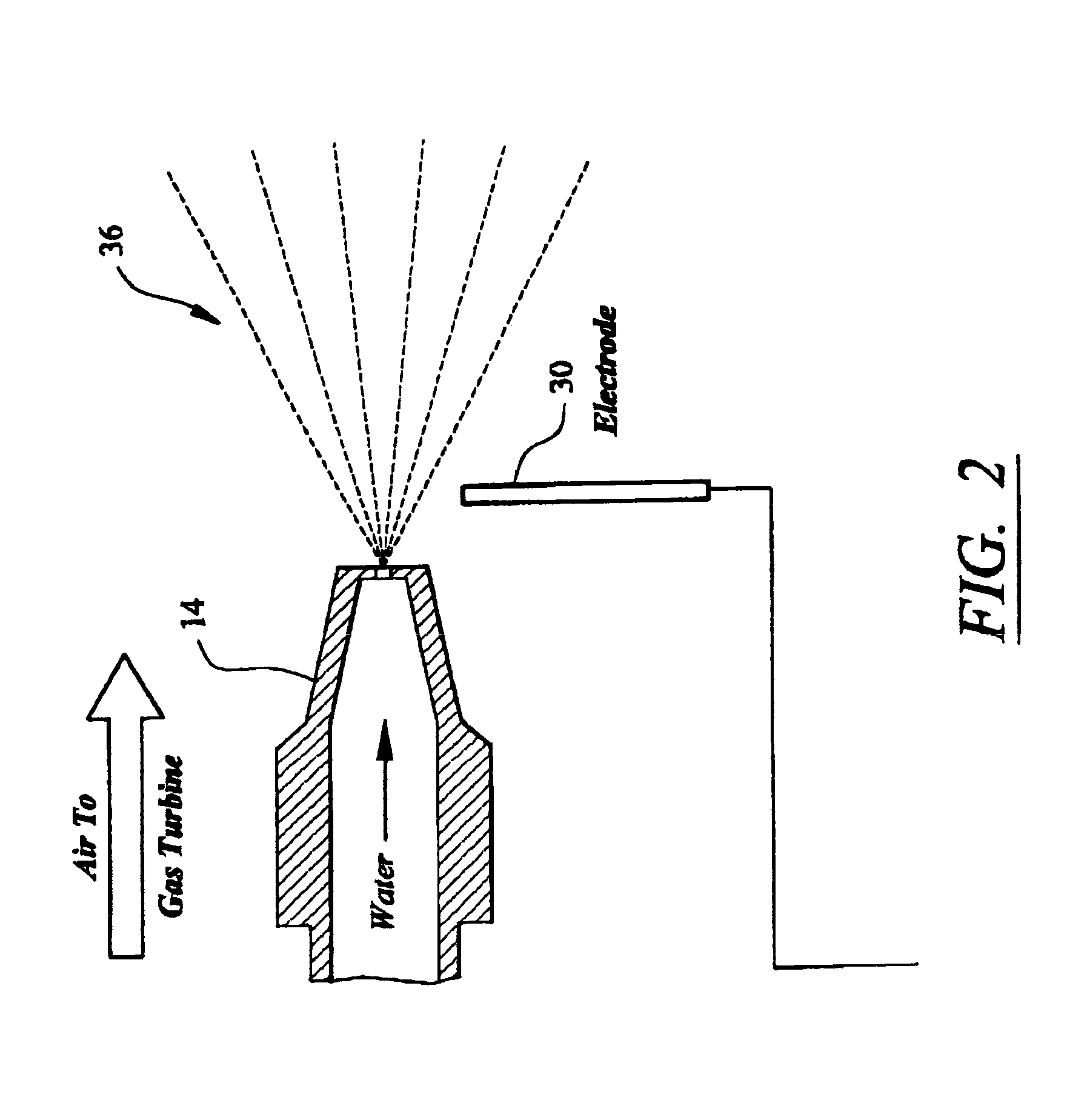
[0014]This invention is directed to systems and methods for evaporating cooling fluids in intake airstreams before droplets of the cooling fluids, or at least a substantial portion of the droplets of cooling fluid, reach a compressor of a turbine engine. In particular, the evaporative cooling system, as shown in FIGS. 1–2, uses electrostatic forces to substantially prevent or limit droplets of a cooling fluid from either agglomerating and settling out of the intake airflow or failing to evaporate. Preventing droplets of a cooling fluid from agglomerating greatly increases the propensity of the droplets to evaporate before flowing into the combustor of a turbine engine.

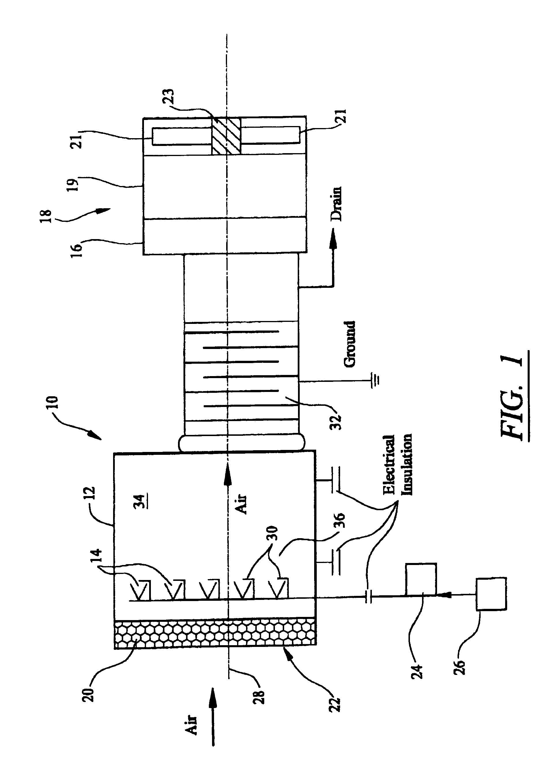
[0015]As shown in FIG. 1, the evaporative cooling system 10 of this invention may be formed from one or more ducts 12 housing one or more fluid emitting devices 14. The duct 12 may be any duct capable of receiving an intake airstream and directing that airstream to a compressor 16 of a turbine engine 18. In at least on...


PUM


Abstract

An evaporative cooling system for applying an electrical charge to a plurality of droplets in an intake airstream of a turbine engine to increase the propensity of the droplets to evaporate before the droplets reach the compressor. The evaporative cooling system may include one or more fluid emitting devices for producing a plurality of droplets and may include one or more electrodes for applying an electrical charge to the plurality of droplets. The evaporative cooling system may also apply an electrical charge to one or more baffles positioned downstream of the fluid emitting devices and upstream from the compressor to collect droplets that have not evaporated before the droplets reach the compressor.

Description

FIELD OF THE INVENTION[0001]This invention is directed generally to turbine engines, and more particularly to evaporative cooling systems for turbine engines.BACKGROUND[0002]Gas turbine engines typically are formed from a compressor, a combustor positioned downstream from the compressor, and a plurality of turbine blades coupled to a rotatable disc positioned downstream from the combustor. The compressor receives air from an inlet and compresses the air before passing the compressed air to the combustor. In the combustor, the compressed air is mixed with fuel, and the mixture is ignited. The combustion gases produced in the compressor are passed to the turbine blades and cause the turbine blades to rotate. The combustion gases are then expelled from the turbine engine through an exhaust outlet at the rear of the turbine engine.[0003]Some gas turbine engines use evaporative cooling systems to cool the intake air upstream of the compressor. Cooling the intake air improves the power an...

Claims


Application Information

Patent Timeline
Patent Type & Authority Patents(United States)
IPC IPC(8): F02C7/055F02C7/143F02C7/04F02C7/12
CPCF02C7/1435F02C7/055
Inventor RITLAND, PAUL DAVID
Owner SIEMENS ENERGY INC
Why Eureka
Try Eureka