Heat exchanger for dehumidifier using liquid desiccant and dehumidifier using liquid desiccant having the same

a technology of liquid desiccant and heat exchanger, which is applied in the field of heat exchanger for a dehumidifier, can solve the problems of lowering heat and mass transfer coefficient and large size of heat exchanger, and achieve the effect of increasing heat transfer efficiency and small siz

Inactive Publication Date: 2014-04-15
KOREA INST OF SCI & TECH
View PDF10 Cites 35 Cited by
  • Summary
  • Abstract
  • Description
  • Claims
  • Application Information

AI Technical Summary

Benefits of technology

[0011]Therefore, an object of the present invention is to provide a heat exchanger for a dehumidifier using a liquid desiccant, the heat exchanger capable of having a small size by increasing heat transfer efficiency.
[0012]Another object of the present invention is to provide a dehumidifier using a liquid desiccant having the heat exchanger, the dehumidifier capable of reducing the size of an entire system.
[0018]In order to reduce a thickness of the liquid desiccant on the surface of the plate, the plate may be hydrophilic surface-coated. And, the heat exchanger body may be surface-treated for enhanced wet property.
[0023]The folded plate may be surface-treated for enhanced wet property.
[0032]In the present invention, due to an extended surface where the liquid desiccant and the air contact with each other, a heat exchange amount in the same area may be increased. This may reduce the entire volume of the heat exchanger.

Problems solved by technology

However, in this case, the liquid desiccant may form a thick liquid film on the surface of the heat exchanger, thereby lowering heat and mass transfer coefficient.
Furthermore, waves may be formed on the surface of the liquid film, or the liquid desiccant may spread to the air due to the unstable liquid film.
This may cause the heat exchanger to have a large size.

Method used


Image

  • Heat exchanger for dehumidifier using liquid desiccant and dehumidifier using liquid desiccant having the same
  • Heat exchanger for dehumidifier using liquid desiccant and dehumidifier using liquid desiccant having the same
  • Heat exchanger for dehumidifier using liquid desiccant and dehumidifier using liquid desiccant having the same

Examples


Embodiment Construction

[0046]Description will now be given in detail of the present invention, with reference to the accompanying drawings.

[0047]Hereinafter, a dehumidifier using a liquid desiccant according to the present invention will be explained in more detail with reference to the attached drawings.

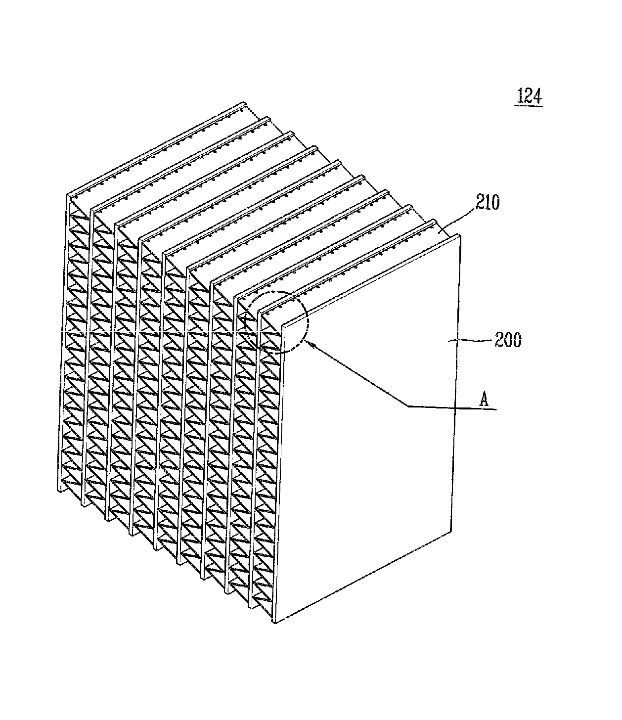
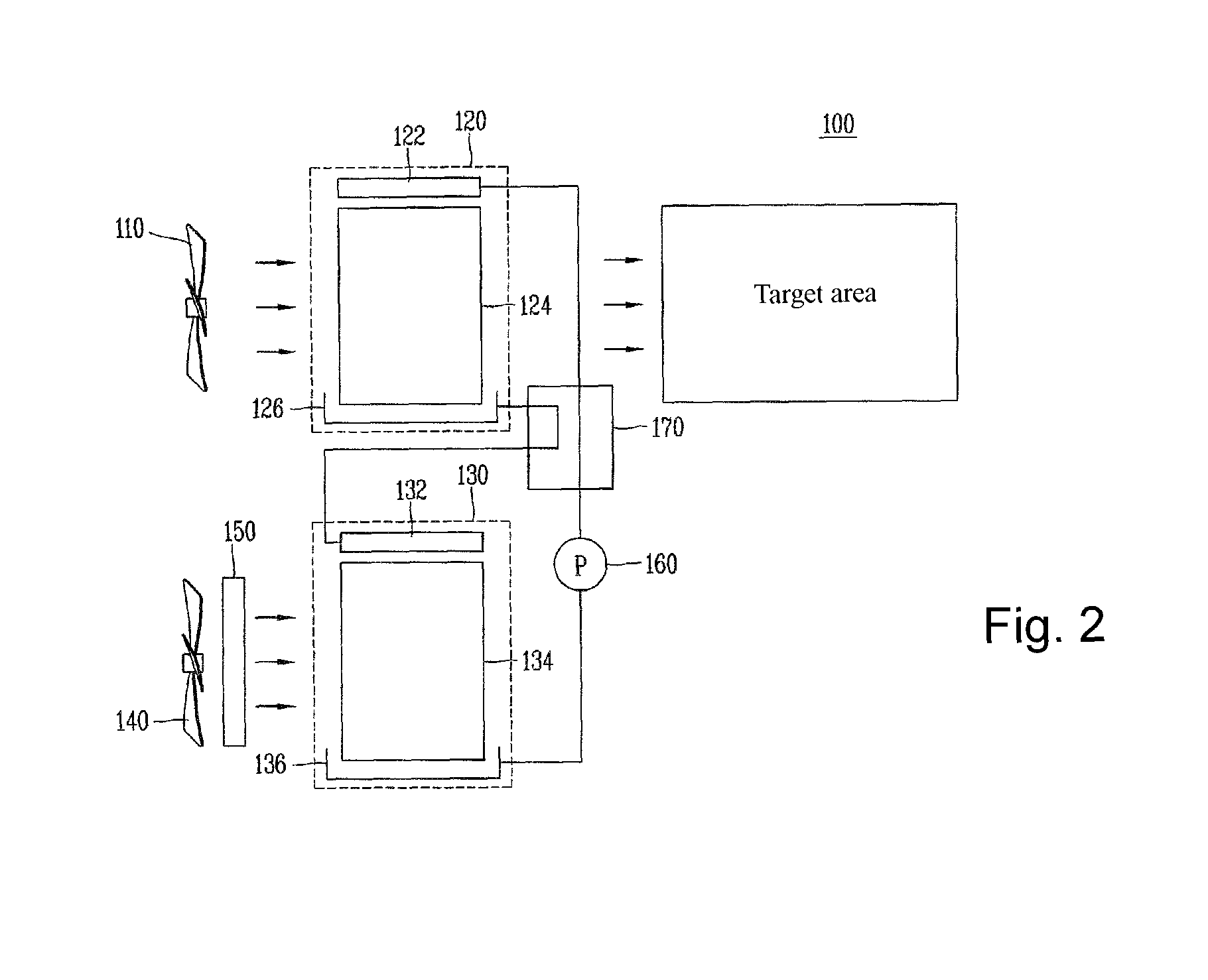
[0048]FIG. 2 is a view schematically showing one example of a dehumidifier using a liquid desiccant according to the present invention.

[0049]Referring to FIG. 2, the dehumidifier using a liquid desiccant 100 according to the present invention comprises a first blow fan 110 configured to suck external air and to supply the air into a system. And, the external air sucked by the first blow fan 110 is blown to a first heat and mass exchange module 120. The first heat and mass exchange module 120 serves to remove moisture from the external air by contacting the external air with the liquid desiccant. An upper header 122 is disposed at an upper side of the first heat and mass exchange module 120, and a first he...


PUM

PropertyMeasurementUnit
hydrophilicaaaaaaaaaa
concentrationaaaaaaaaaa
temperatureaaaaaaaaaa

Abstract

Disclosed are a heat exchanger for a dehumidifier using a liquid desiccant and a dehumidifier using a liquid desiccant having the same. The heat exchanger for a dehumidifier using a liquid desiccant, comprises: a plurality of plate-type heat exchanger bodies to which a heat transfer medium flows through flow paths formed therein; and a plurality of plates extending between the respective heat exchanger bodies, and inclined with respect to the surfaces of the heat exchanger bodies.

Description

RELATED APPLICATION[0001]The present disclosure relates to subject matter contained in priority Korean Application No. 10-2009-0093482, filed on Sep. 30, 2009, which is herein expressly incorporated by reference in its entirety.BACKGROUND OF THE INVENTION[0002]1. Field of the Invention[0003]The present invention relates to a heat exchanger for a dehumidifier using a liquid desiccant and a dehumidifier using a liquid desiccant having the same, and particularly, to a dehumidifier capable of absorbing moisture from the air by using a liquid desiccant, and a heat exchanger for the dehumidifier.[0004]2. Background of the Invention[0005]A dehumidifier using a liquid desiccant is an apparatus for obtaining dry air by absorbing moisture from the air by spraying a liquid desiccant having a high concentration to the air. The dehumidifier using a liquid desiccant is configured to be consecutively operated by circulating a liquid desiccant sprayed into the air, an object to be dried. Since the ...

Claims


Application Information

Patent Timeline
Patent Type & Authority Patents(United States)
IPC IPC(8): B01D47/00
CPCF28D1/05383F28F1/126B01D53/263F24F2003/144F24F2003/1435B01D2259/65F28D2021/0038F28F17/005F24F3/1417F24F3/147F24F3/14F28F13/04F28F19/02
Inventor CHANG, YOUNG SOOLEE, DAE-YOUNG
Owner KOREA INST OF SCI & TECH
Why Eureka
Try Eureka