Pneumatic tire

a pneumatic tire and tire technology, applied in the field of pneumatic tires, can solve the problems of increasing the temperature of the tire in the pneumatic tire, the sidewall reinforcing layer reaching a very high temperature, and the tread portion breaking, so as to facilitate the separation of airflow and accelerate the heat exchange

Active Publication Date: 2010-02-18
BRIDGESTONE CORP
View PDF15 Cites 33 Cited by
  • Summary
  • Abstract
  • Description
  • Claims
  • Application Information

AI Technical Summary

Benefits of technology

[0097]In the above described configurations, as the pneumatic tire 1 rotates, an airflow a flowing along substantially in the tire circumferential direction in a manner relative thereto is generated on the outer circumferential face 3a of the tire side portion 3 as shown in FIGS. 4 and 5. By flowing on the outer circumferential face 3a after being turned into a turbulent flow by one of the turbulent-flow generating projections 10, this airflow a carries out active heat exchange with this outer circumferential face 3a.
[0098]In detailed description of a flow of the turbulent flow flowing on the outer circumferential face 3a, the airflow is turned into an upward-and-downward turbulent flow which goes upward in a position where the turbulent-flow generating projection 10 exists, and goes downward in a position where the turbulent-flow generating projection 10 does not exist.
[0099]Particularly, in a condition that each of the turbulent-flow generating projections 10 includes the edge portion 10f, a function of separating an airflow is effected, the airflow being caused, by centrifugal force, to flow from the inner circumferential side to the outer circumferential side with rotation of the pneumatic tire 1. This separated airflow can accelerate heat exchange by hitting the tire side portion 3 after turning into a strong downward flow.
[0100]Additionally, in a condition that each of the turbulent-flow generating projections 10 includes the edge portion 10g, it is made easier for an airflow to be separated from the tire side portion 3 when the airflow goes over the turbulent-flow generating projections 10 with rotation of the pneumatic tire 1. Consequently, the airflow once separated from the tire side portion 3 can accelerate heat exchange with the tire side portion 3 by being turned into a turbulent flow by a negative pressure generated in the rearward side (downstream) of the turbulent-flow generating projection 10 in the tire rotation direction, the turbulent flow rapidly falling onto and hitting the tire side portion 3.
[0101]Additionally, in a condition that the front wall angle θ of each of the turbulent-flow generating projections 10 is set in the range of 70° to 110°, an angle β of air separated at the edge portion 10g in the upward-and-downward turbulent flow a1 can be made large to some extent, and the upward-and-downward turbulent flow a1 hits the outer circumferential face 3a after turning into a strong downward flow in the downstream of the turbulent-flow generating projection 10, whereby active heat exchange with the tire surface is carried out. Thus, decrease of tire temperature can be reliably facilitated by the turbulent-flow generating projections 10 provided on the outer circumferential face 3a, and durability can be enhanced.
[0102]Additionally, in a condition that the projection-width cross-sectional shape of each of the turbulent-flow generating projections 10 is left-right symmetric, leftward and rightward distances respectively to both surfaces of the turbulent-flow generating projection 10 from a center position of the turbulent-flow generating projection 10 in the projection-width cross-section thereof are equal, whereby a heat storage amount inside the turbulent-flow generating projection 10 can be reduced to the smallest possible level,

Problems solved by technology

In general, increase of a tire temperature in a pneumatic tire is considered unfavorable in terms of durability since the increase accelerates time-dependent changes such as a change in material property, and leads to breakage of a tread portion and the like when the tire travels at high speed.
Decreasing a tire temperature has been a challenge for enhancing durability particularly in the cases of an off-the-road radial tire (ORR) and a truck / bus radial tire (TBR) which are used under heavy loads, and in the case of a run-flat tire when travelling in a punctured state (when travelling with an inflation pressure thereof at 0 kPa).
For example, in a run-flat tire having a sidewall reinforcing layer whose cross-sectional shape in a tread-width direction is crescent, when the tire travels in a punctured state, deformation in a tire radius direction concentrates on the sidewall reinforcing layer, and causes the sidewall reinforcing layer to reach a very high temperature, whereby durability is severely affected.
However, in the case of a conventional pneumatic tire in which the above described reinforcing member is provided, provision of the reinforcing member increases a tire weight, and leads to occurrence of an unintended additional failure such as separation (detachment) of the reinforcing member.
There has been a problem that normal traveling performances such as driving stability and riding comfort are deteriorated thereby.
Particularly in the case of a run-flat tire, it has been feared that vertical spring (elasticity in a vertical direction of the tire) when the tire travels with a normal inflation pressure becomes high, and thereby deteriorates normal traveling performances.
However, efficient heat release of a tire side portion has not been achieved only by the simple increase of the tire surface area since a rubber member with low heat conductivity is arranged in the outer circumferential side of the pneumatic tire.

Method used


Image

  • Pneumatic tire
  • Pneumatic tire
  • Pneumatic tire

Examples


first embodiment

[0071]Next, one example of the pneumatic tire according to the present invention will be described with reference to the drawings. Note that, in the following description of the drawings, the same or similar parts will be denoted by the same or similar reference numerals. However, it should be noted that, since the drawings are schematic, dimensional proportions and the like are different from actual ones. Accordingly, specific dimensions and the like should be judged in consideration of the following description. Additionally, it goes without saying that there are some parts having dimensional relationships and dimensional proportions different from one drawing to another.

(Configuration of Pneumatic Tire)

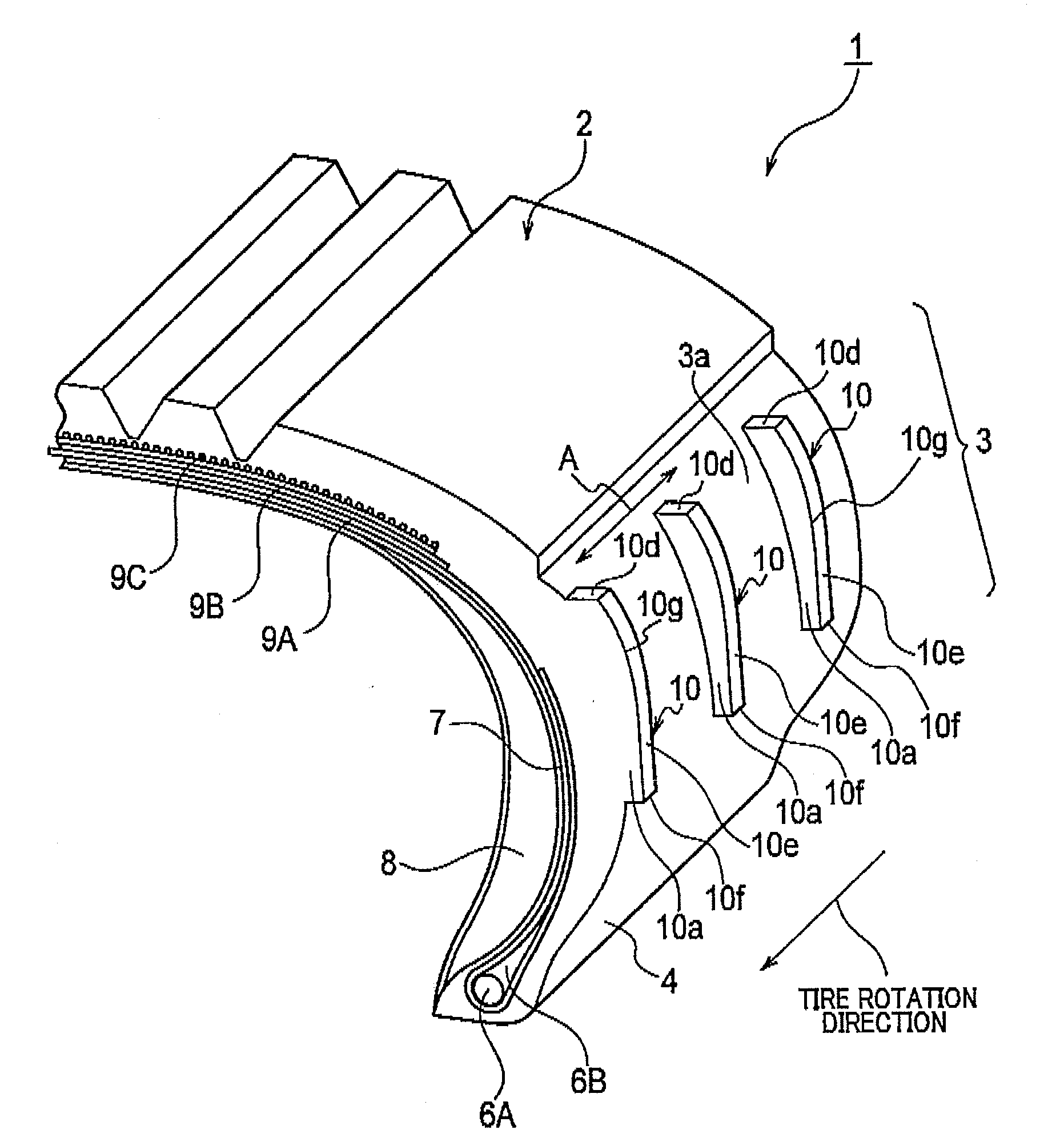
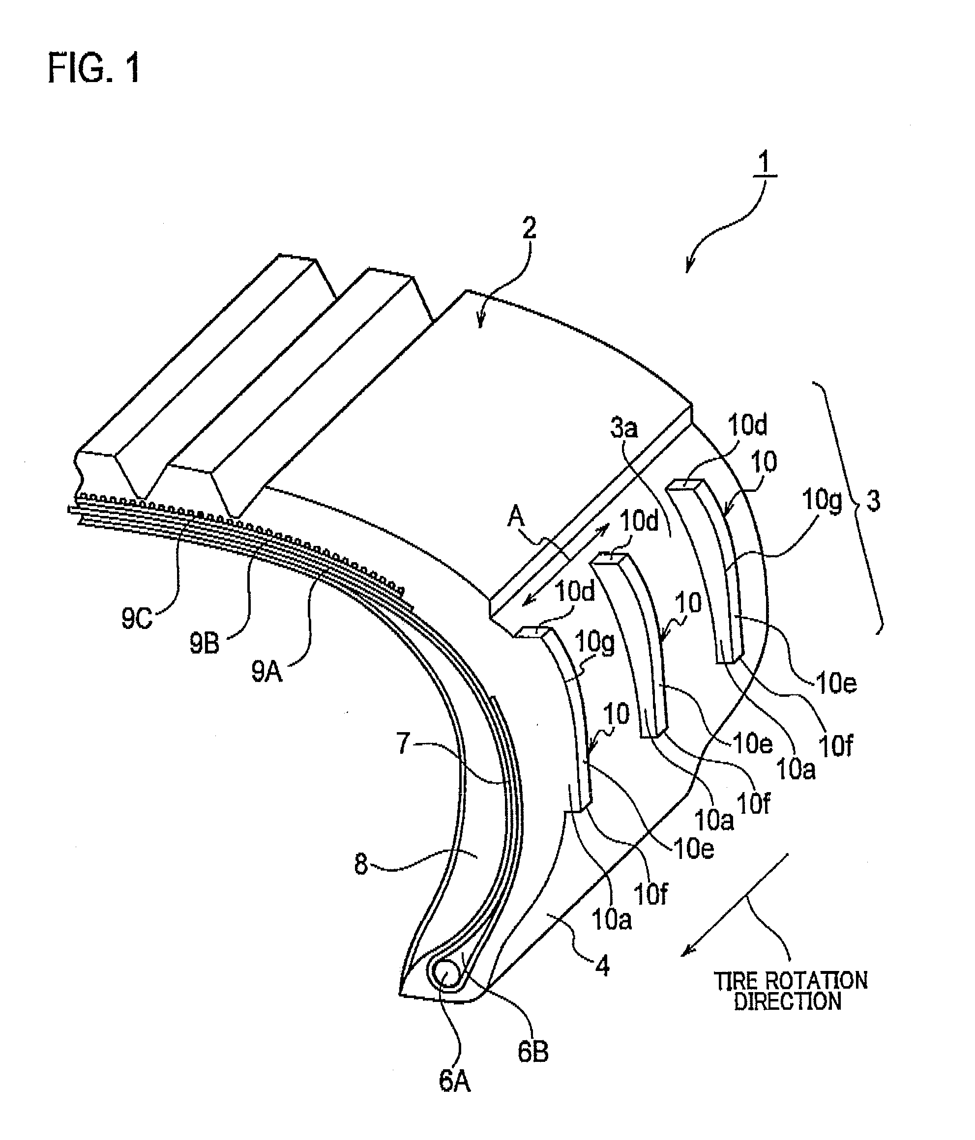
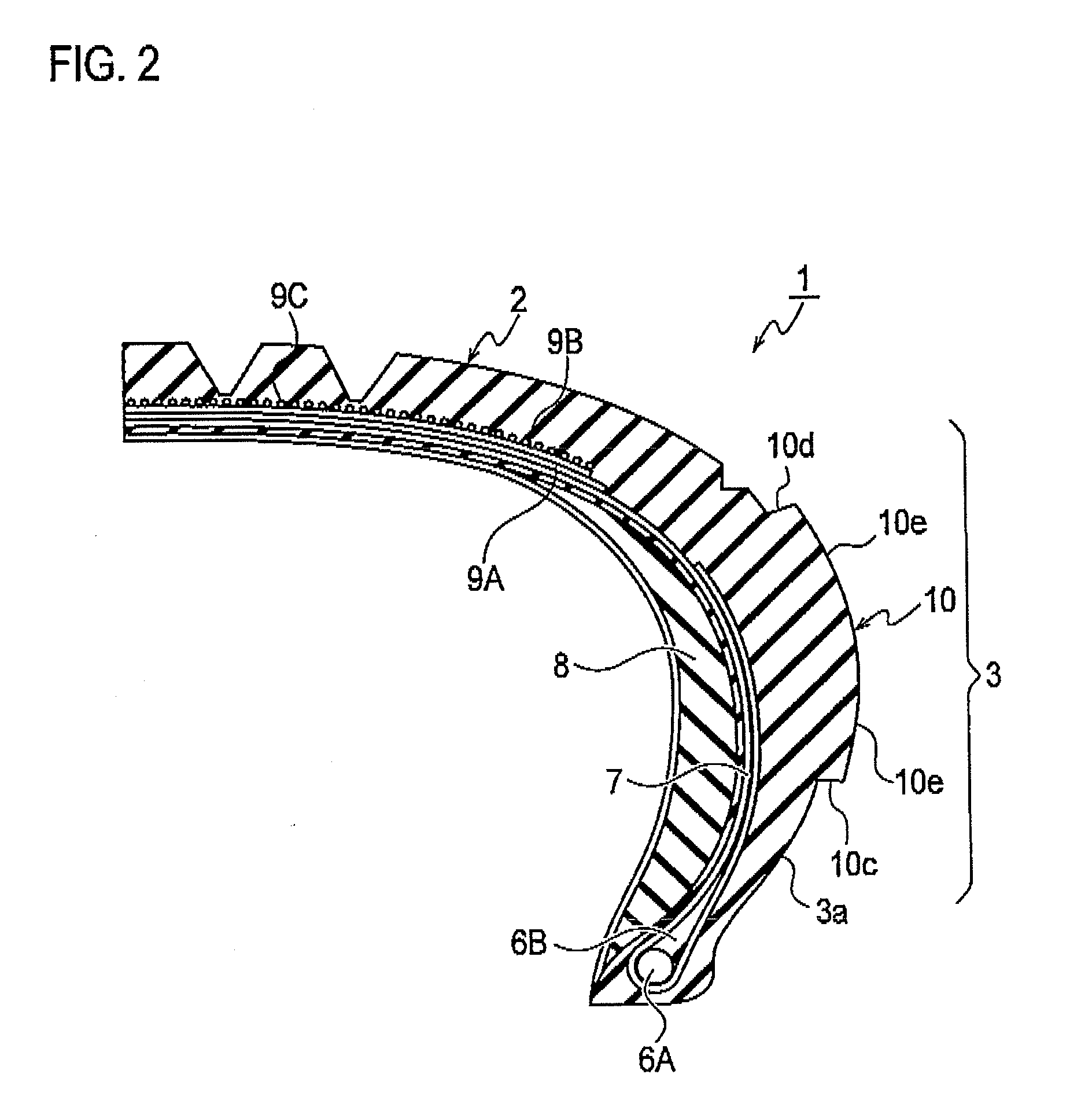
[0072]Firstly, configurations of a pneumatic tire according to a first embodiment will be described with reference to FIGS. 1 and 2. FIG. 1 is an exploded perspective view showing a part of the pneumatic tire according to the first embodiment; FIG. 2, a tread-width direction cross-...

modification example 1

[0110]Firstly, each turbulent-flow generating projection according to a modification example 1 will be described with reference to FIG. 7. FIG. 7 is a side view showing a cross-section of the turbulent-flow generating projection 10A according to the modification example 1.

[0111]As shown in FIG. 7, a projection-width cross-sectional shape of the turbulent-flow generating projection 10A is left-right symmetric. The projection-width cross-sectional shape of this turbulent-flow generating projection 10A is trapezoidal. Additionally, the front wall angle θ1 and the rear wall angle θ2 are both set to an angle exceeding 90°.

[0112]In a condition that the projection-width cross-sectional shape of the turbulent-flow generating projection 10A is thus trapezoidal, generation of cracks attributable to degradation of angled portions can be prevented as much as possible since angled portions having an angle exceeding 90° are eliminated from the turbulent-flow generating projection 10A, Additionall...

modification example 2

[0113]Next, each, turbulent-flow generating projection according to a modification example 2 will be described with reference to FIG. 8. FIG. 8 is a side view showing a cross-section of the turbulent-flow generating projection 10B according to the modification example 2.

[0114]As shown in FIG. 8, a projection-width cross-sectional shape of the turbulent-flow generating projection 10B is left-right symmetric. The projection-width cross-sectional shape of this turbulent-flow generating projection 10B is triangular. In other words, the front wall angle θ1 and the rear wall angle θ2 are both set to an angle exceeding 90°.

[0115]Specifically, the turbulent-flow generating projection 10B is constituted of the front wall face 10a, the rear wall face 10b, the inner side face 10c and the outer side face 10d, and does not include the upper face 10e. That is, the edge portion 10g is formed between the front wall face 10a and the rear wall face 10b of the turbulent-flow generating projection 10B....


PUM


Abstract

The present invention relates to a pneumatic tire 1 in which turbulent-flow generating projections 10 each extending from an inner circumference side to an outer circumference side are provided on a outer circumferential face 3a which is tire surface of tire side portion 3 at intervals in a tire circumferential direction. Each of the turbulent-flow generating projections 10 includes an edge portion 10g when being viewed in a cross-sectional shape taken along a direction perpendicular to an extending direction thereof, and a front wall angle θ formed between a front wall face 10a of each turbulent-flow generating projection 10 and the tire surface (outer circumferential face 3a) is set in the range of 70° to 110°, the front wall face being hit by an airflow.

Description

[0001]The present invention relates to a pneumatic tire, particularly, a pneumatic tire capable of decreasing temperature in a tire side portion prone to occurrence of degradation.BACKGROUND ART[0002]In general, increase of a tire temperature in a pneumatic tire is considered unfavorable in terms of durability since the increase accelerates time-dependent changes such as a change in material property, and leads to breakage of a tread portion and the like when the tire travels at high speed. Decreasing a tire temperature has been a challenge for enhancing durability particularly in the cases of an off-the-road radial tire (ORR) and a truck / bus radial tire (TBR) which are used under heavy loads, and in the case of a run-flat tire when travelling in a punctured state (when travelling with an inflation pressure thereof at 0 kPa).[0003]For example, in a run-flat tire having a sidewall reinforcing layer whose cross-sectional shape in a tread-width direction is crescent, when the tire trav...

Claims


Application Information

Patent Timeline
Patent Type & Authority Applications(United States)
IPC IPC(8): B60C23/18
CPCB60C11/0309B60C11/042B60C17/0045B60C2011/1338B60C17/0009B60C13/02B60C11/04B60C11/13B60C13/00B60C17/00
Inventor YAMAGUCHI, MASASHI
Owner BRIDGESTONE CORP
Why Eureka
Try Eureka