
High efficiency dual cycle internal combustion engine with steam power recovered from waste heat

a dual-cycle, high-efficiency technology, applied in steam use, machines/engines, mechanical equipment, etc., can solve the problems of inefficiency of the system for recovering waste exhaust heat and waste heat from the combustion chamber coolant in a dual-cycle engine, and achieve the effects of improving operating efficiency, high efficiency and increasing efficiency

Active Publication Date: 2009-08-20
THERMAL POWER RECOVERY
View PDF84 Cites 34 Cited by
  • Summary
  • Abstract
  • Description
  • Claims
  • Application Information

AI Technical Summary

Benefits of technology

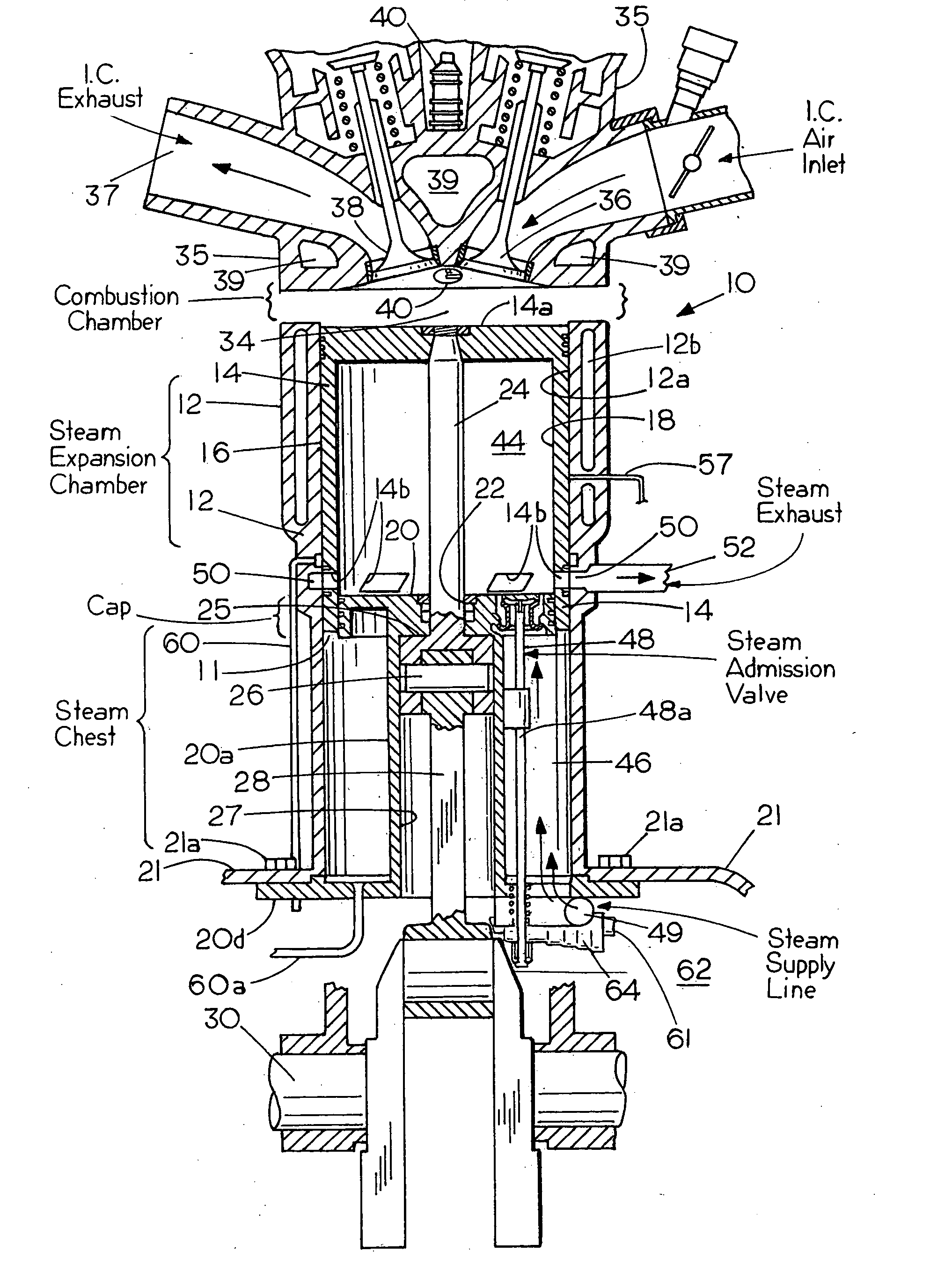
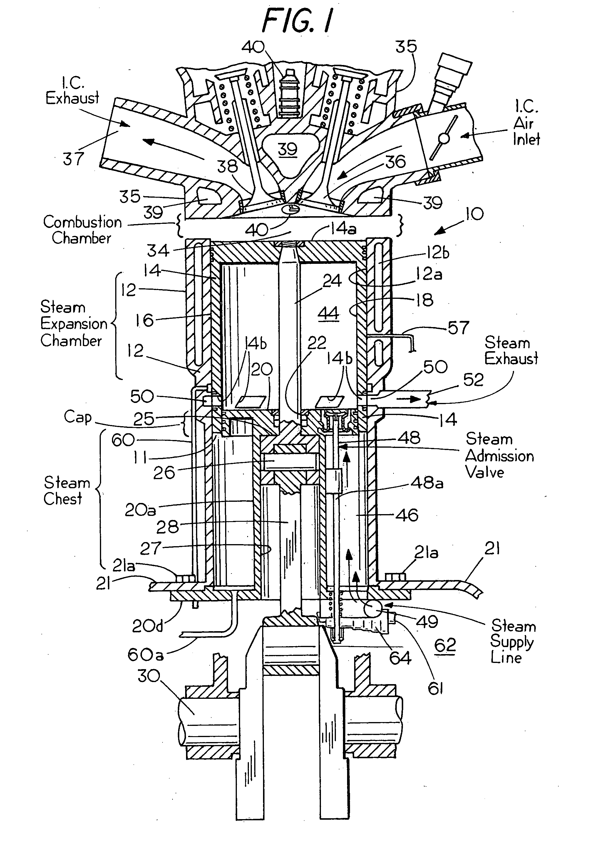
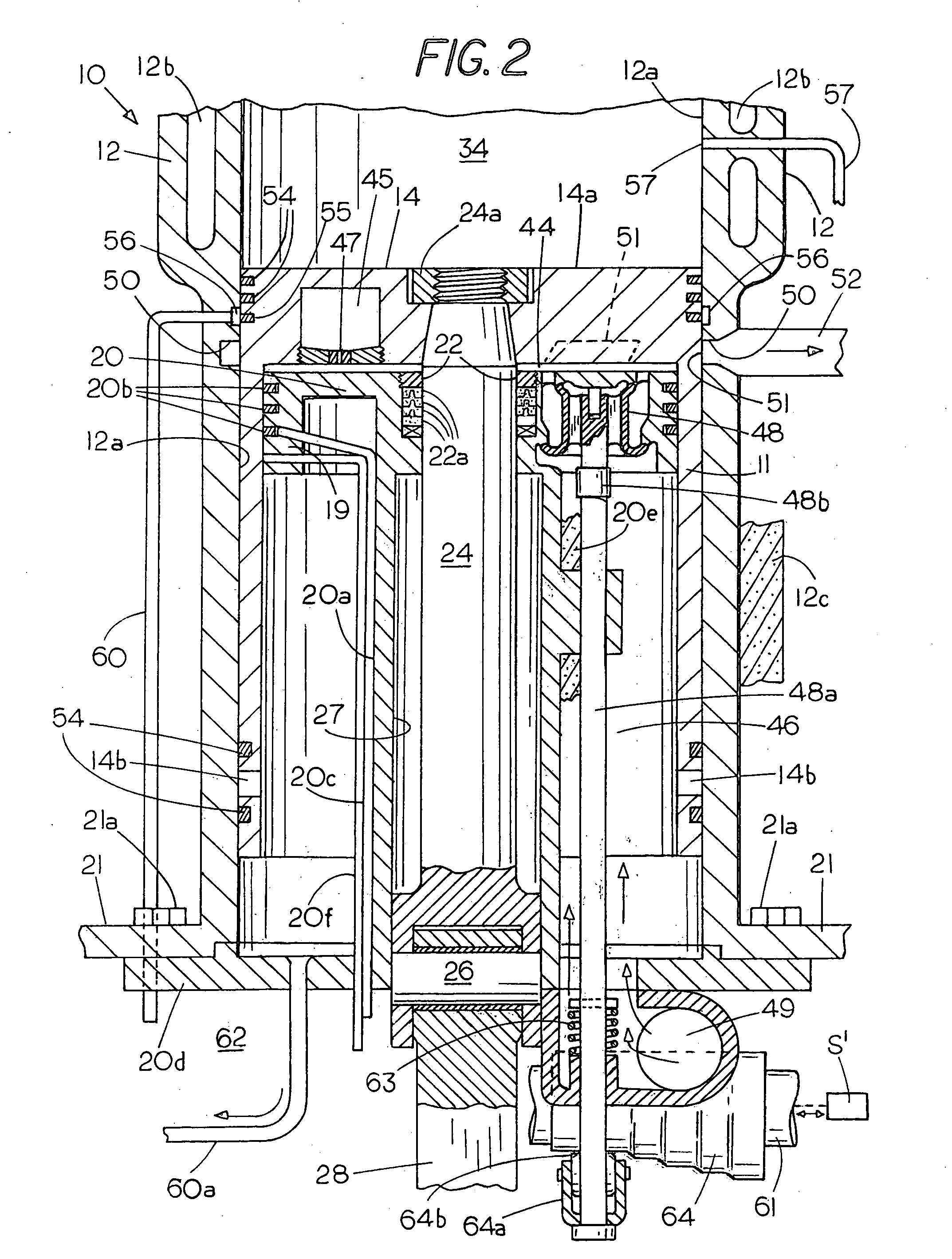
[0035]This invention concerns a high efficiency composite internal combustion and steam engine especially suited for use in cars and trucks which includes one or more combustion chambers for burning fuel to power a piston by combustion as well as at least one expandable chamber within the engine that is powered by steam generated from what would have been waste heat from the combustion chamber. Previous systems for recovering waste exhaust heat and waste heat from the combustion chamber coolant in a dual cycle engine have been inefficient. To overcome this and other deficiencies, the present invention provides a combined cycle engine which employs the advantage of using high temperature, i.e. superheated steam with a way of accomplishing uniflow steam operation inwardly of each internal combustion piston to improve operating efficiency as well as benefiting from a way to provide variable steam cutoff through the use of one or a pair of series connected, inwardly retractable, steam pressure balanced valves that are located in a cylinder cap which is sealed within each piston operating in cooperation with steam recompression and a provision for achieving effective clearance volume changes that vary with engine speed to thereby further increase efficiency and the specific power output from the waste heat energy recovered. In one example of a cutoff control, a camshaft is coupled for changing the phase of one of a pair of steam admission valves to vary valve overlap, thus providing continuous regulation of the steam cutoff to further reduce specific fuel consumption. Depending upon the application of the engine, the cylinder cap which is placed adjacent to a steam exhaust port can be unheated but if advantageous is capable of being heated to the temperature of the superheated steam supply or, if desired, can have a device for providing an intermediate controlled degree of heating to provide optimum power. Engine coolant can be evaporated in the engine-cooling jacket to form steam which is then superheated by I.C. exhaust gases within an engine exhaust manifold for powering the steam expansion chamber within each piston. Heating of the cylinder cap makes it possible in some engine applications to achieve high efficiencies which surpass those in what is known as a uniflow steam engine to provide additional power from waste combustion heat; an efficiency level that is much higher than in an ordinary counterflow steam engine. The engine also has the flexibility needed under non-uniform steam generator pressure and engine load conditions that occur in vehicles through a provision for variable steam displacement. Another aspect of the invention concerns a more efficient way to recover combustion heat that is contained in the combustion chamber coolant and in the I.C. exhaust gas using an exhaust powered superheater comprising an engine exhaust manifold for supplemental combustion of unburned fuel while also providing for the direct conduction of the heat produced in the combustion chamber to increase the enthalpy of expanding steam within the steam expansion chamber inside of each piston. The invention thus provides an improved heat recovery, heat exchange, steam generator and superheater system for generating steam with a way to better construct a steam expansion chamber, steam cylinder head and valving, heated steam exhaust area, a provision for steam recompression to admission pressure inside of a combustion piston so as to achieve an effective zero clearance and a gain in mean Rankine cycle temperature along with a steam supply arrangement that is able to act on each piston within an I.C. engine so as to more effectively economize on fuel, make a more efficient combined gas and steam engine, balance the steam displacement with steam generator output to use steam more efficiently, and provide other features that will be apparent from the following description.

Problems solved by technology

Previous systems for recovering waste exhaust heat and waste heat from the combustion chamber coolant in a dual cycle engine have been inefficient.

Method used


Image

  • High efficiency dual cycle internal combustion engine with steam power recovered from waste heat
  • High efficiency dual cycle internal combustion engine with steam power recovered from waste heat
  • High efficiency dual cycle internal combustion engine with steam power recovered from waste heat

Examples


example

Calculation of Power Recovered

[0096]A one-cylinder 564 cc (34.4 cubic inches), 4-cycle internal combustion engine (bore 96 mm×stroke 78 mm) producing 13.5 horsepower (572.6 Btu / min) at 3000 rpm and exhibiting a brake efficiency of 21% will require an energy input rate of 2526.7 Btu / min and will reject 2154.1 Btu / min to the steam generator 104. For a boiler efficiency of 70%, which is merely average for modern monotube steam generators, 1507.8 Btu / min will be transferred to heat the feed water. The sustained evaporation is the ratio of the waste heat recovered to the enthalpy change Δh as the feed water (or steam) passes through the steam generator. At 800 psia and 800° F. with saturated feed water at 14.7 psia and 212° F., the enthalpy change is 1218.5 Btu / lb (1398.6-180.07). The resulting sustained evaporation rate for supply steam ms is then 1.24 lb / min.:

ms=wasteheatrecoveredΔh=1507.8Btu / min1218.5Btu / lb=1.24lb / min

Rankine cycle analysis based on the internal energy changes of non-f...


PUM


Abstract

A high efficiency combined cycle internal combustion and steam engine includes a cylinder having a piston mounted for reciprocation therein with an internal combustion chamber outward of the piston, a fixed cylinder cap sealingly and slideably mounted within the piston and a steam expansion / recompression chamber inside the piston adjacent the cylinder cap. The cylinder cap can be unheated or heated externally to reduce condensation of steam entering the steam chamber from a steam generator fired by waste combustion heat. Steam remaining in the cylinder when a steam exhaust valve closes at the top center position is recompressed during an inward stroke of the piston up to admission pressure prior to admitting the next charge of steam. One valve or a pair of retractable steam inlet valves connected in series within the cylinder cap act in cooperation with steam recompression and clearance volume to achieve an effective zero steam chamber clearance and a gain in mean Rankine cycle temperature to maximize efficiency. The amount of steam admitted each outward stroke is continuously regulated, e.g. by shifting the phase of one steam admission valve of a pair to vary their overlap for determining the steam mass admitted during each cycle to reduce specific fuel consumption. Other valves balance steam displacement with the steam generator output to use steam more efficiently. Engine coolant can be evaporated in a combustion chamber cooling jacket to form steam which is then superheated in a combustion exhaust manifold.

Description

[0001]This application is a continuation-in-part of Ser. No. 12 / 075,042 filed Mar. 7, 2008. The applicants claim the benefit of the following provisional and non-provisional applications entitled INTERNAL COMBUSTION ENGINE WITH AUXILIARY STEAM POWER RECOVERED FROM WASTE HEAT, Ser. No. 60 / 905,732 filed Mar. 7, 2007; Ser. No. 12 / 075,042 filed Mar. 7, 2008 (Pub. No. 2008 / 0216408A1); Ser. No. 61 / 192,254 filed Sep. 17, 2008 and Ser. No. 61 / 194,608 filed Sep. 29, 2008 which are incorporated herein by reference.FIELD OF THE INVENTION[0002]This invention relates to internal combustion engines with supplemental steam power obtained from waste combustion heat and to a combination internal combustion (I.C.) engine and steam engine.BACKGROUND[0003]Internal combustion engines although highly developed, dependable and relied upon for almost all road transportation throughout the world generally lose about 72-75% of the fuel heating value through radiation, engine coolant and exhaust. The measured...

Claims


Application Information

Patent Timeline
Patent Type & Authority Applications(United States)
IPC IPC(8): F01K17/00
CPCF01K15/02F01K23/10Y02T10/166F02G5/02Y02E20/14F01K23/14Y02T10/12
Inventor HARMON, SR., JAMES V.HARMON, JR., JAMES V.HARMON, STEPHEN C.
Owner THERMAL POWER RECOVERY
Learn More