Solid oxide fuel cell stack having an integral gas distribution manifold

a fuel cell and gas distribution manifold technology, applied in the field of solid oxide fuel cell systems, can solve the problems of heavy duty, dimensionally larger, thick and massive, etc., and achieve the effects of improving the durability and reliability of the sofc power unit, preventing leakage therebetween, and high strength

Active Publication Date: 2007-10-25
BATTELLE MEMORIAL INST +1
View PDF5 Cites 32 Cited by
  • Summary
  • Abstract
  • Description
  • Claims
  • Application Information

AI Technical Summary

Benefits of technology

[0016] It is a still further object of the invention to improve the durability and reliability of an SOFC power unit.
[0017] Briefly described, an SOFC stack in accordance with the invention includes an integral individual stack manifold containing all of the gas pathways necessary for proper supply and exhaust of fuel gas and cathode air to and from the stack chimneys. The stack lacks its own intermediate base plate, as in the prior art, and instead is mounted directly to the surface of the individual stack manifold to which it is hermetically joined by a high temperature bonding seal such as glass, ceramic adhesive, or braze, thus preventing leakage therebetween. The manifold includes one or more high strength alloy flanges at the inlet and outlet ports for coupling to system distributary manifolds via conventional, proven high temperature sealing joints using bolts or clamps. The gas streams entering and leaving the individual manifold are routed through a minimum of four such ports (anode in / out and cathode in / out). Preferably, an individual stack manifold is fabricated of a ferritic stainless steel for low cost and to match the CTE of the stack, and may be formed in a one-piece casting, a combination of multiple castings and stamped plates metallurgically joined (brazed or welded together), or stamped from sheet metal stock.
[0018] Preferably, an individual stack manifold includes fin structures extending into adjacent fuel gas and cathode air chambers to enhance thermal balancing of gas temperatures. Heat exchange may be improved still further by configuring the manifold to have a plurality of interleaved anode and cathode gas supply cavities.

Problems solved by technology

There are multiple drawbacks to this design.
First, the base plate, fabricated from ferritic stainless steel to match the coefficient of thermal expansion (CTE) of the fuel cell stack components, must be very thick and massive to attempt to maintain a uniform compressive load on the gasket.
Second, the system manifold must have sufficient structural rigidity to attempt to maintain a uniform compressive load on the gasket against the base plate, requiring expensive alloys for providing such rigidity at the high SOFC operating temperatures.
Third, the stack compressive loading mechanism must provide more load than is required for stack seal integrity in order to provide sufficient load for the gasket, and is therefore heavier duty and dimensionally larger than would otherwise be necessary.
When a prior art SOFC power system is constructed to account for all these considerations, distribution of gases to the chimneys may still be suboptimal due to the system manifold requirements; further, leaking of the compressive gasket may still occur with unacceptable frequency, allowing combustible gas to mix with hot air, resulting in localized overheating or system failure.
The problem with the prior concepts is that they were discrete devices which added to the packaging complexity and cost of the system.

Method used


Image

  • Solid oxide fuel cell stack having an integral gas distribution manifold
  • Solid oxide fuel cell stack having an integral gas distribution manifold
  • Solid oxide fuel cell stack having an integral gas distribution manifold

Examples


Embodiment Construction

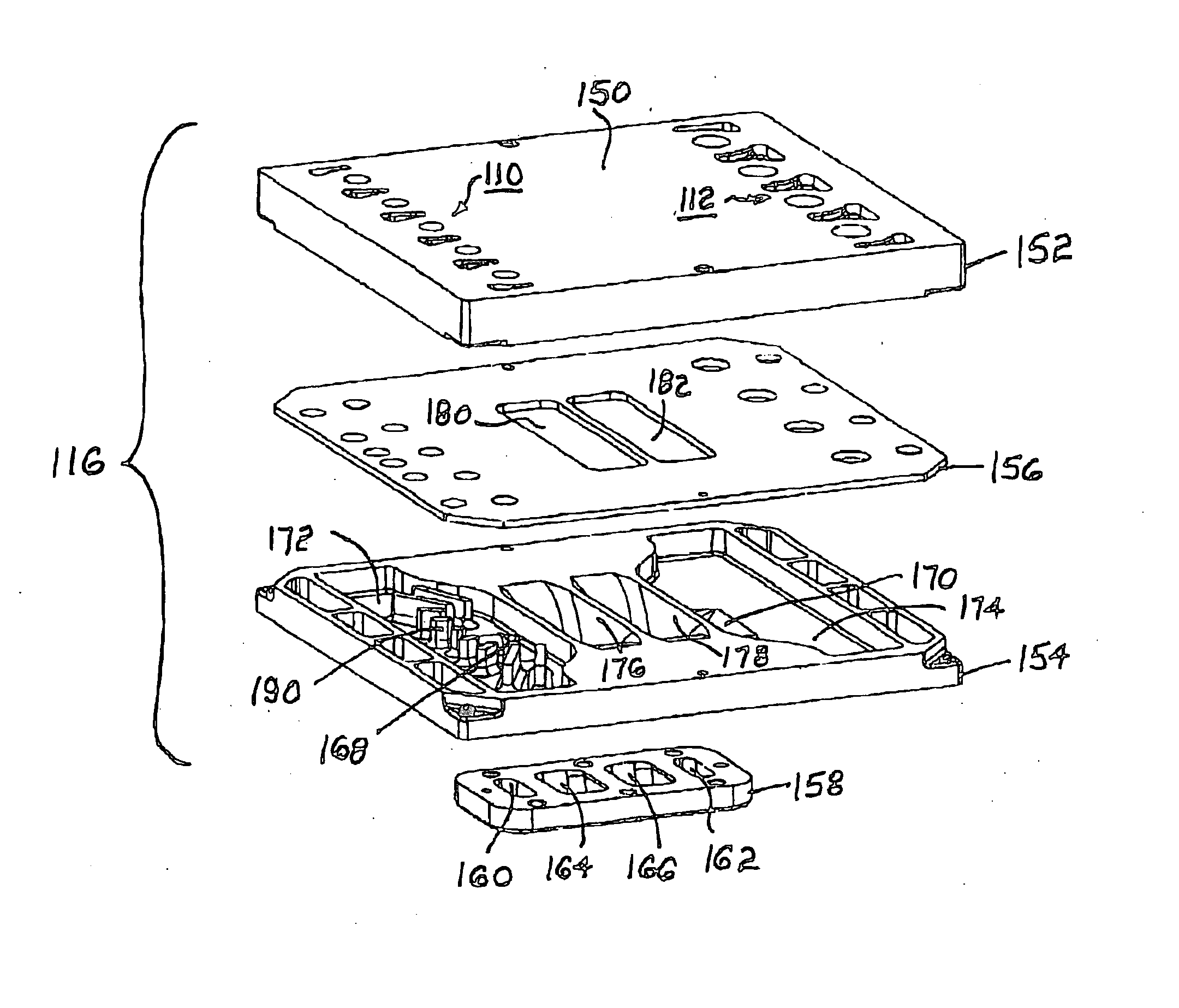
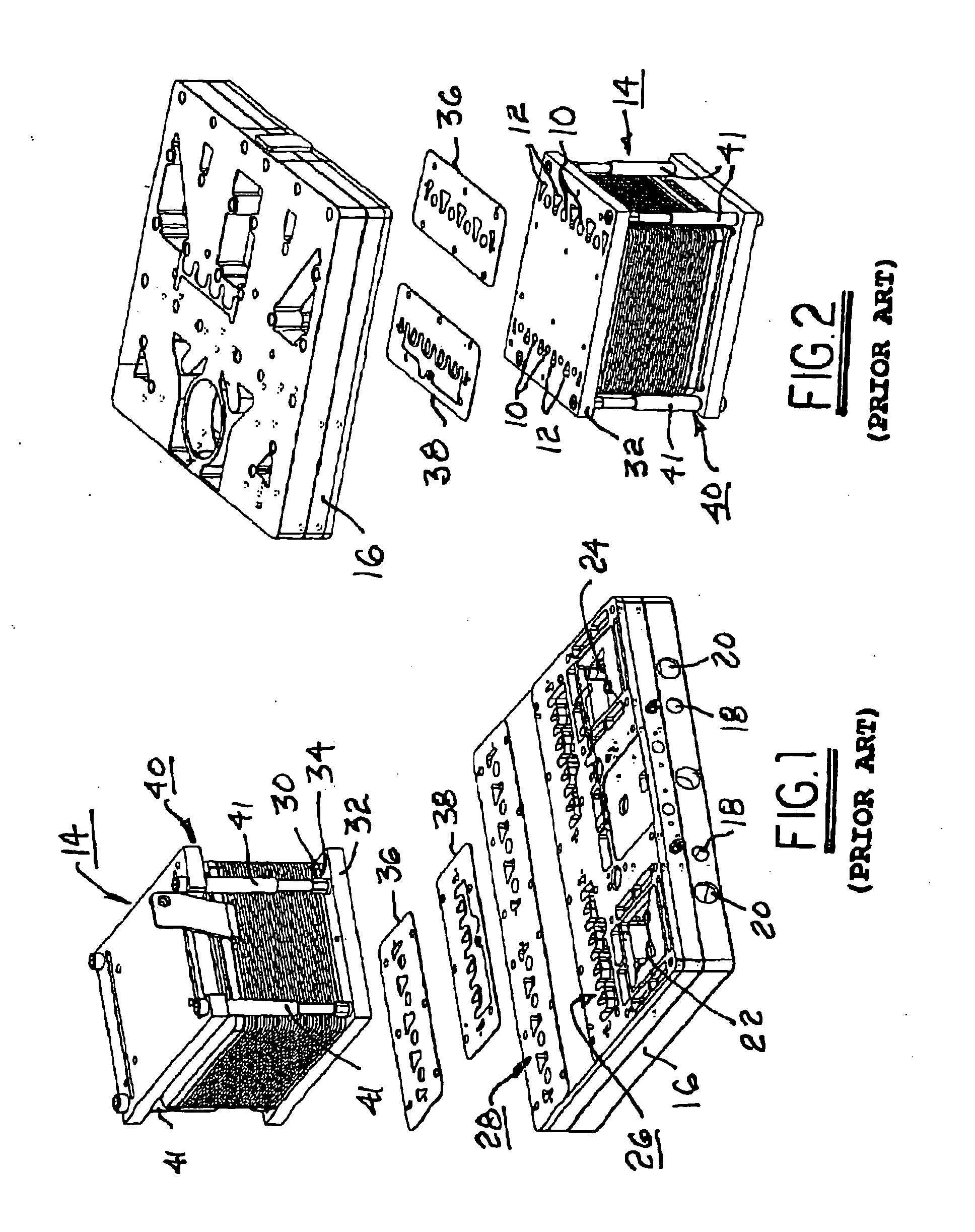
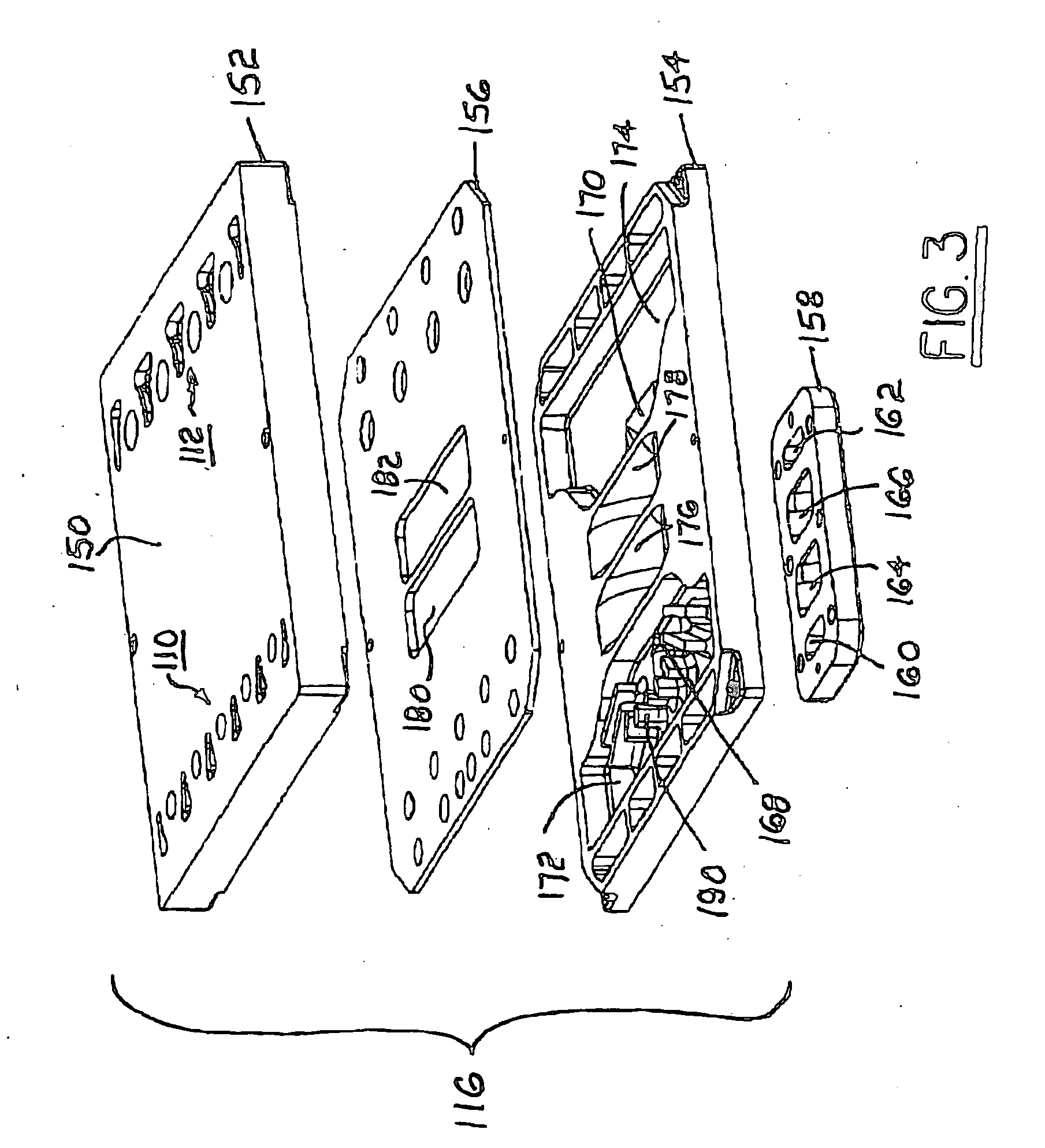
[0031] The benefits and advantages of an integral individual manifold for a fuel cell stack in accordance with the invention may be better appreciated by first considering a prior art assembly of a fuel cell stack and a separate gas distributing manifold, and the shortcomings thereof.

[0032] Referring to FIGS. 1 and 2, in the prior art, distribution of anode fuel gas and air into and out of the anode and cathode distribution chimneys 10,12 of a fuel cell stack 14 (such as an SOFC stack) is carried out by a separate, complex gas distributing manifold 16, such as is disclosed in U.S. Pat. No. 6,967,064 B2. Manifold 16 routes these gases from respective anode and cathode inlet ports 18,20, through tubular heat exchangers (not shown but mounted to sockets 22,24) for partial equalization of temperature differences between the hot reformate fuel and the incoming air, and thence to outlet and return ports 26,28 on the surface of manifold 16. (Manifold 16 as shown is formed to accommodate t...


PUM

PropertyMeasurementUnit
operating temperatureaaaaaaaaaa

Abstract

An SOFC stack module including an integral individual stack manifold containing all of the gas pathways necessary for supply and exhaust of fuel gas and cathode air to and from the stack chimneys. The stack is mounted and hermetically joined directly to the manifold without an intermediate base plate. Flanges at the inlet and outlet ports couple to system distributary manifolds via high temperature sealing joints. The manifold preferably is fabricated of a ferritic stainless steel, and may be formed in a one-piece casting, a combination of multiple castings and stamped plates metallurgically joined (brazed or welded together), or stamped from sheet metal stock. Preferably, the manifold includes fin structures extending into adjacent fuel gas and cathode air chambers to enhance balancing of temperatures by heat exchange therebetween. Heat exchange may be further improved by configuring the manifold to have a plurality of interleaved anode and cathode gas supply chambers.

Description

[0001] This invention was made with United States Government support under Government Contract / Purchase Order No. DE-FC26-02NT41246. The Government has certain rights in this invention.TECHNICAL FIELD [0002] The present invention relates to fuel cells; more particularly, to solid oxide fuel cell systems having manifold distribution of gases to and from one or more fuel cell stacks; and most particularly, to a fuel cell stack assembly having a gas distribution manifold formed integrally with the stack. BACKGROUND OF THE INVENTION [0003] A solid oxide fuel cell (SOFC) stack assembly is the power-producing component in an SOFC electric power plant such as an auxiliary power unit (APU) for a vehicle, a stationary power generating unit (SPU), a combined heat and power unit (CHP), or other such system. In a practical and manufacturable SOFC power system, the stack assembly typically is manufactured as a stand-alone component mounted into the power system for ease of assembly, service, and...

Claims


Application Information

Patent Timeline
Patent Type & Authority Applications(United States)
IPC IPC(8): H01M8/24H01M2/08H01M8/02H01M8/04
CPCH01M8/028H01M8/0286H01M8/04074Y02E60/50H01M8/2425H01M8/2465H01M8/248H01M8/242H01M8/2432H01M8/2483H01M8/0271
Inventor HALTINER, KARL J. JR.VORDONIS, JAMES S.O'BRIEN, JOHN F.
Owner BATTELLE MEMORIAL INST
Why Eureka
Try Eureka