Oil supplying apparatus for vehicle

a technology for supplying apparatus and oil, which is applied in the direction of positive displacement liquid engine, lubrication of auxiliaries, piston pumps, etc., can solve the problems of delay in hydraulic actuator operation, unstable operation of hydraulic actuator,

Inactive Publication Date: 2009-12-17
AISIN SEIKI KK
View PDF12 Cites 32 Cited by
  • Summary
  • Abstract
  • Description
  • Claims
  • Application Information

AI Technical Summary

Benefits of technology

[0008]According to an aspect of the present invention, an oil supplying apparatus for a vehicle includes an engine driven mechanical oil pump, a hydraulic actuator operated by pressure of oil supplied from the engine driven mechanical oil pump to the hydraulic actuator, an engine lubrication device lubricating each member of the engine with the oil supplied from the engine driven mechanical oil pump, and a priority flow valve selectively establishing priority flow and secondary flow conditions when a low oil pressure is working on the hydraulic actuator and when a high oil pressure is working on the hydraulic actuator, respectively, the priority flow condition allowing an oil supply from the engine driven mechanical oil pump to the hydraulic actuator with priority over an oil supply from the engine driven mechanical oil pump to the engine lubrication device, the secondary flow condition allowing the oil supply from the engine driven mechanical oil pump to the engine lubrication device.

Problems solved by technology

Consequently, when a hydraulic actuator or similar system is provided on a hydraulic circuit of the aforementioned oil supplying apparatus, problems including delay in operation of the hydraulic actuator may occur.
In particular, it is unavoidable that the operation of the hydraulic actuator is unstable due to insufficient fluid pressure when the engine speed is not high enough, for example, at engine start, because the mechanical oil pump is driven by the engine.
However, application of the electric oil pump for assisting the mechanical oil pump causes increased cost and weight, and a tight installation space.

Method used


Image

  • Oil supplying apparatus for vehicle
  • Oil supplying apparatus for vehicle
  • Oil supplying apparatus for vehicle

Examples


Embodiment Construction

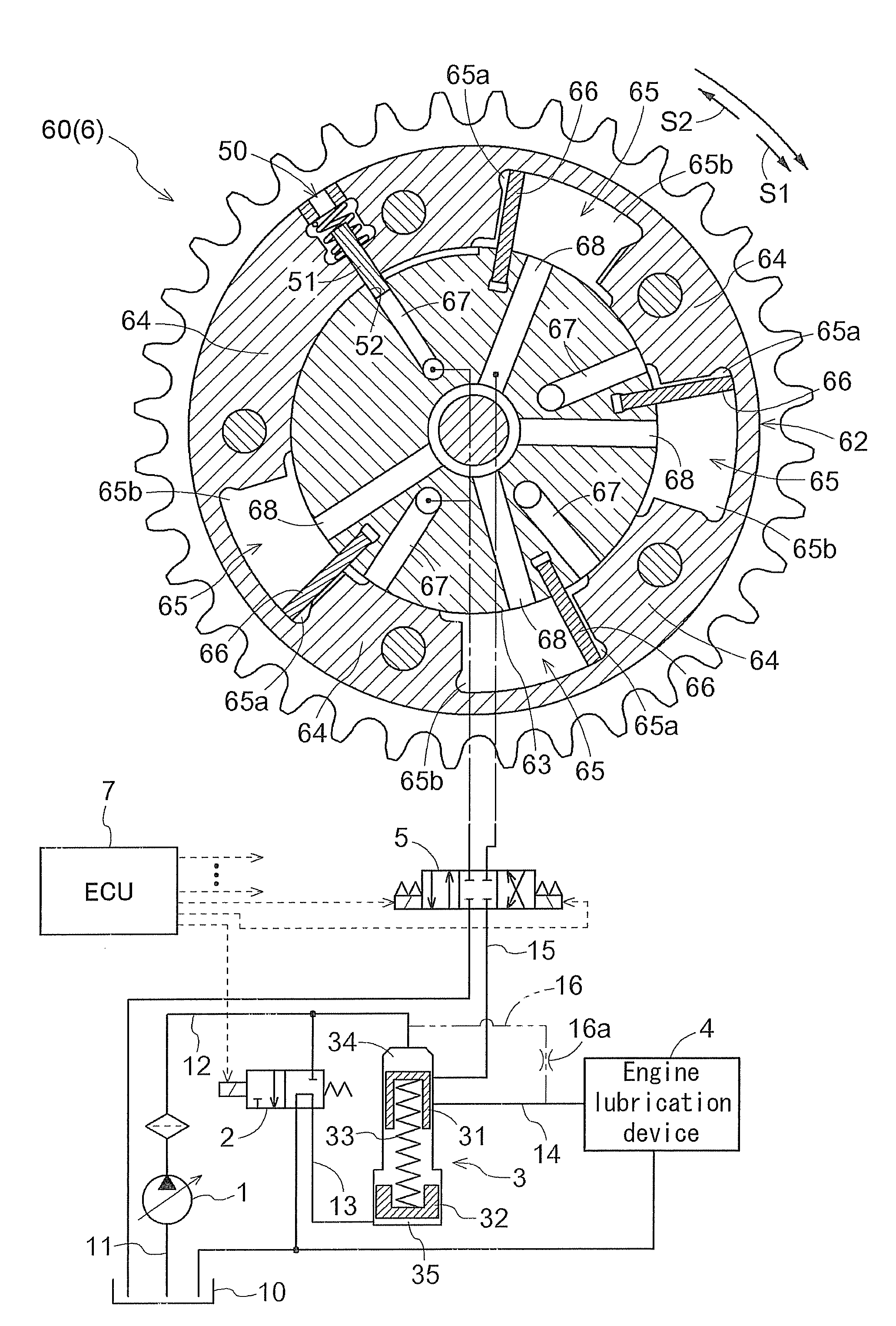
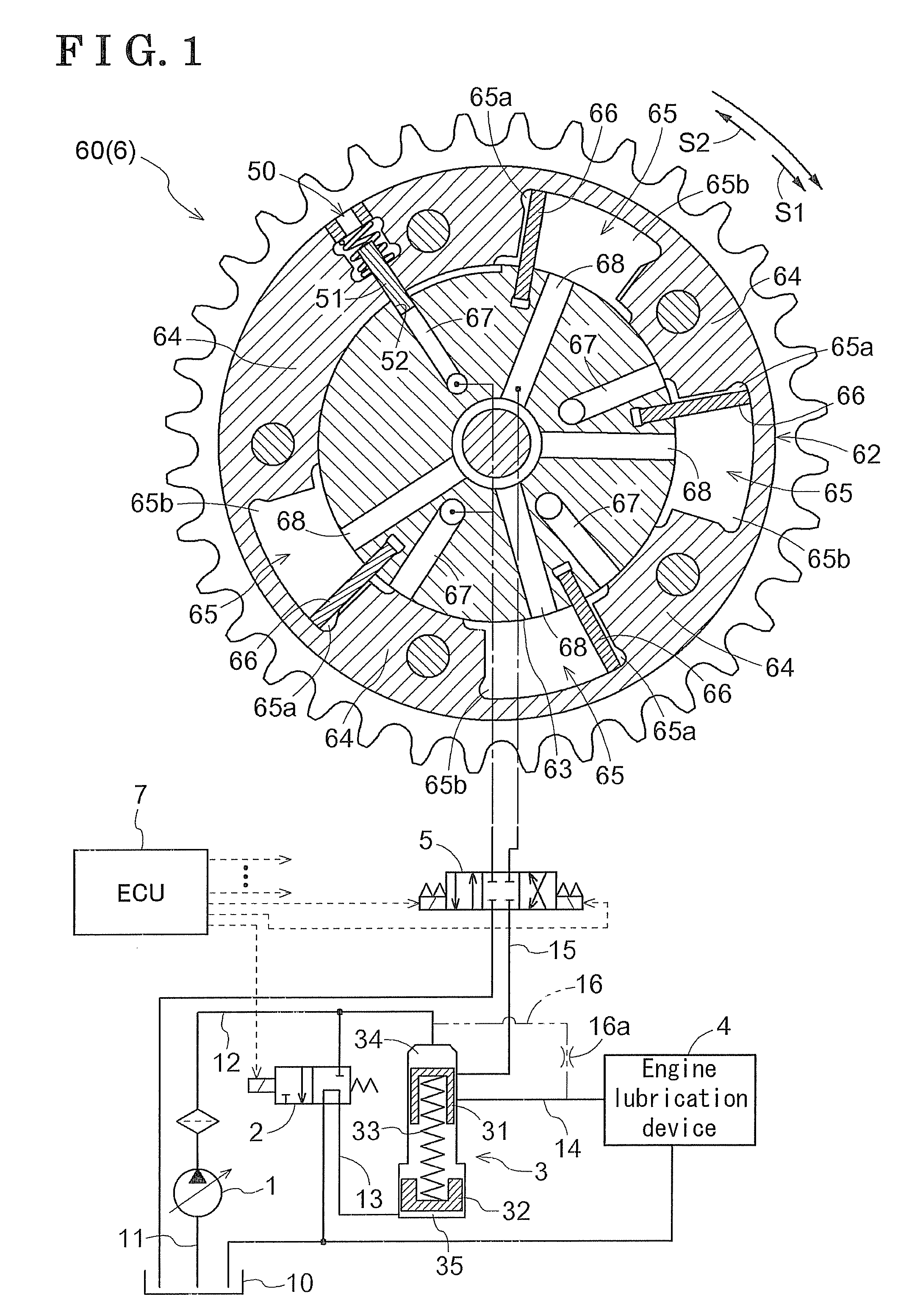
[0015]A first embodiment of the present invention will be explained with reference to the illustrations as follows. Terms used in the embodiments for indicating the directions, such as upper, lower, should be understood to be as viewed in the illustrations. As shown in FIG. 1, in an oil supplying apparatus for a vehicle of this embodiment, oil is supplied from an engine driven mechanical oil pump 1 (hereinafter referred to as an oil pump 1) coupled to an output shaft of an engine to an engine lubrication device 4 that lubricates each member of the engine and to a valve timing control system 6 serving as a hydraulic actuator. The oil supplying apparatus of this embodiment further includes a priority flow valve 3 for supplying priority flow from the oil pump 1 to the valve timing control system 6 by regulating secondary flow from the oil pump 1 to the engine lubrication device 4 when a low fluid pressure is working on the valve timing control system 6, and for supplying the secondary ...


PUM


Abstract

An oil supplying apparatus for a vehicle, includes an engine driven mechanical oil pump, a hydraulic actuator operated by pressure of oil supplied from the engine driven mechanical oil pump to the hydraulic actuator, an engine lubrication device lubricating each member of the engine with the oil supplied from the engine driven mechanical oil pump, and a priority flow valve selectively establishing priority flow and secondary flow conditions when a low oil pressure is working on the hydraulic actuator and when a high oil pressure is working on the hydraulic actuator, respectively, the priority flow condition allowing an oil supply from the engine driven mechanical oil pump to the hydraulic actuator with priority over an oil supply from the engine driven mechanical oil pump to the engine lubrication device, the secondary flow condition allowing the oil supply from the engine driven mechanical oil pump to the engine lubrication device.

Description

CROSS REFERENCE TO RELATED APPLICATIONS[0001]This application is based on and claims priority under 35 U.S.C. §119 to Japanese Patent Application 2008-154564, filed on Jun. 12, 2008, the entire content of which is incorporated herein by reference.FIELD OF THE INVENTION[0002]The present invention relates to an oil supplying apparatus for a vehicle.BACKGROUND[0003]One of known oil supplying apparatuses for a vehicle is a lubrication oil supplying apparatus for an engine. The lubrication oil supplying apparatus includes a supply passage to a crank system for supplying lubrication oil discharged from an oil pump, which is a fixed displacement oil pump, driven by the engine to a main bearing of a crank shaft. The lubrication oil supplying apparatus for the engine also includes a supply passage to a valve train for supplying the lubrication oil discharged from the oil pump to lubricating portions of the valve train. In the lubrication oil supplying apparatus for the engine, an orifice for...

Claims


Application Information

Patent Timeline
Patent Type & Authority Applications(United States)
IPC IPC(8): F04B49/00F04B35/00F01M1/02
CPCF01L1/34F01M1/12F01L1/3442
Inventor ONO, HISASHINISHIDA, YUKI
Owner AISIN SEIKI KK
Why Eureka
Try Eureka