Non-woven, self-wrapping thermal sleeve

a self-wrapping, non-woven technology, applied in the field of sleeves, can solve the problems of unsightly tape appearance, high cost, and high labor intensity of tape application, and achieve the effect of reducing the risk of injury, avoiding injury, and avoiding injury

Inactive Publication Date: 2009-12-17
FEDERAL MOGUL POWERTAIN LLC
View PDF11 Cites 42 Cited by
  • Summary
  • Abstract
  • Description
  • Claims
  • Application Information

AI Technical Summary

Benefits of technology

[0012]According to another aspect of the invention, the outermost reflective layer can be provided to extend completely circumferentially about the substrate to circumferentially encapsulate the substrate, thereby providing complete circumferential thermal protection to the enclosed wires while also maintaining the sleeve in a closed configuration while in use.
[0013]According to yet another aspect of the invention, the sleeve can have a foil tape applied over a seam extending along the length of the sleeve to circumferentially encapsulate the substrate with a continuous reflective foil layer to provide complete circumferential thermal protection to the enclosed wires and to maintain the sleeve in a circumferentially closed configuration while in use.

Problems solved by technology

Unfortunately, applying tape is labor intensive, and thus, costly.
In addition, the appearance of the tape can be unsightly, particularly over time as the tape wears, which in turn, can result in the wires being partially exposed.
Further, in service, tape can provide difficulties in readily accessing the wound wires.
If wrapped and fastened, additional costs are incurred for the fasteners and in attaching the fasteners to the sleeves.
If tubular and non-wrappable, installation problems can arise.
Further, additional labor and / or processes are typically involved to secure the sleeves about the wires.
As such, although these sleeves generally prove useful in protecting the wires from exposure to heat in use, they can be relatively costly to manufacture, given that they are woven, knitted or braided, with additional costs being incurred to attach fasteners to the sleeves and to secure the sleeves about the wires.

Method used


Image

  • Non-woven, self-wrapping thermal sleeve
  • Non-woven, self-wrapping thermal sleeve
  • Non-woven, self-wrapping thermal sleeve

Examples


Embodiment Construction

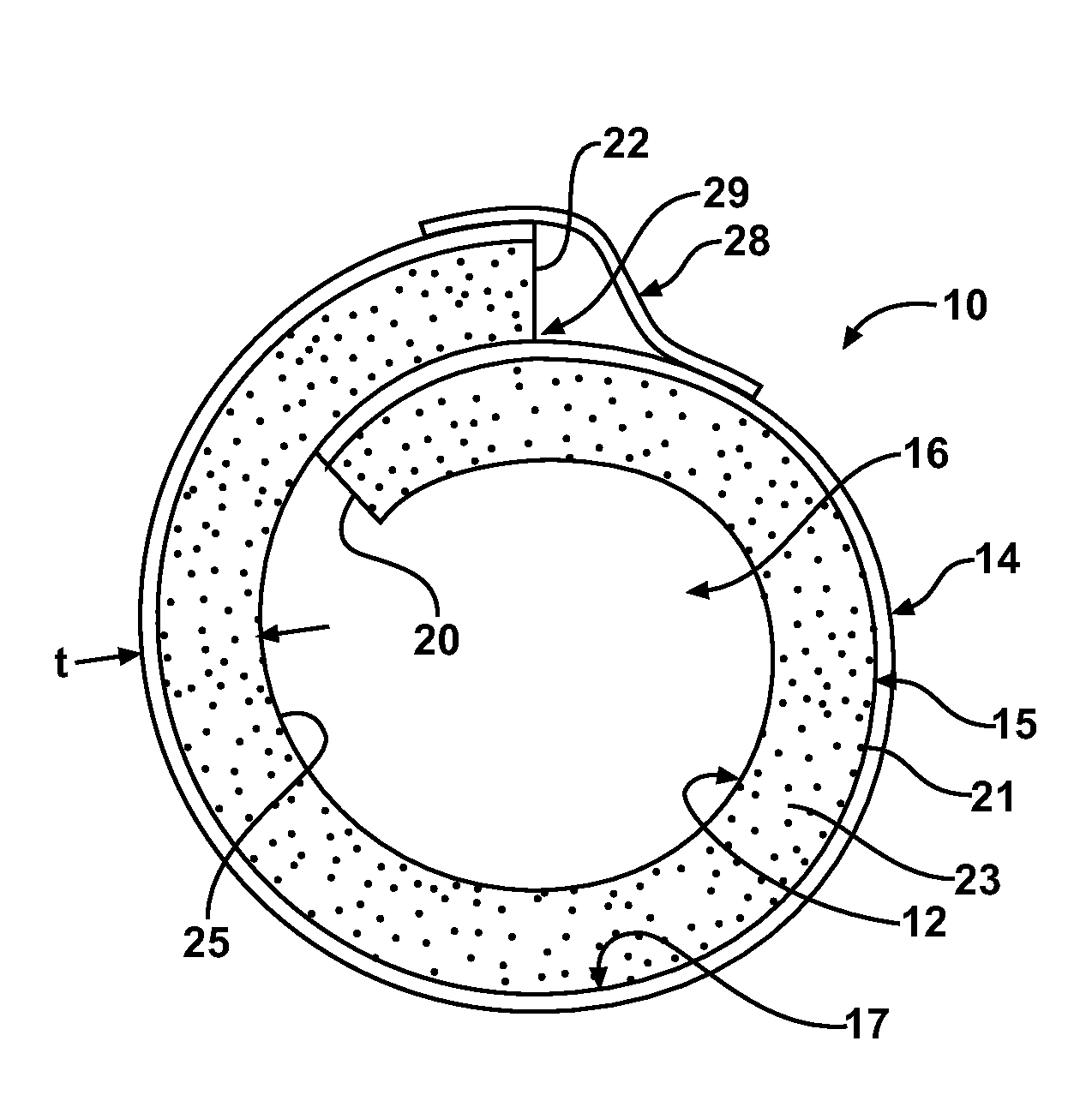
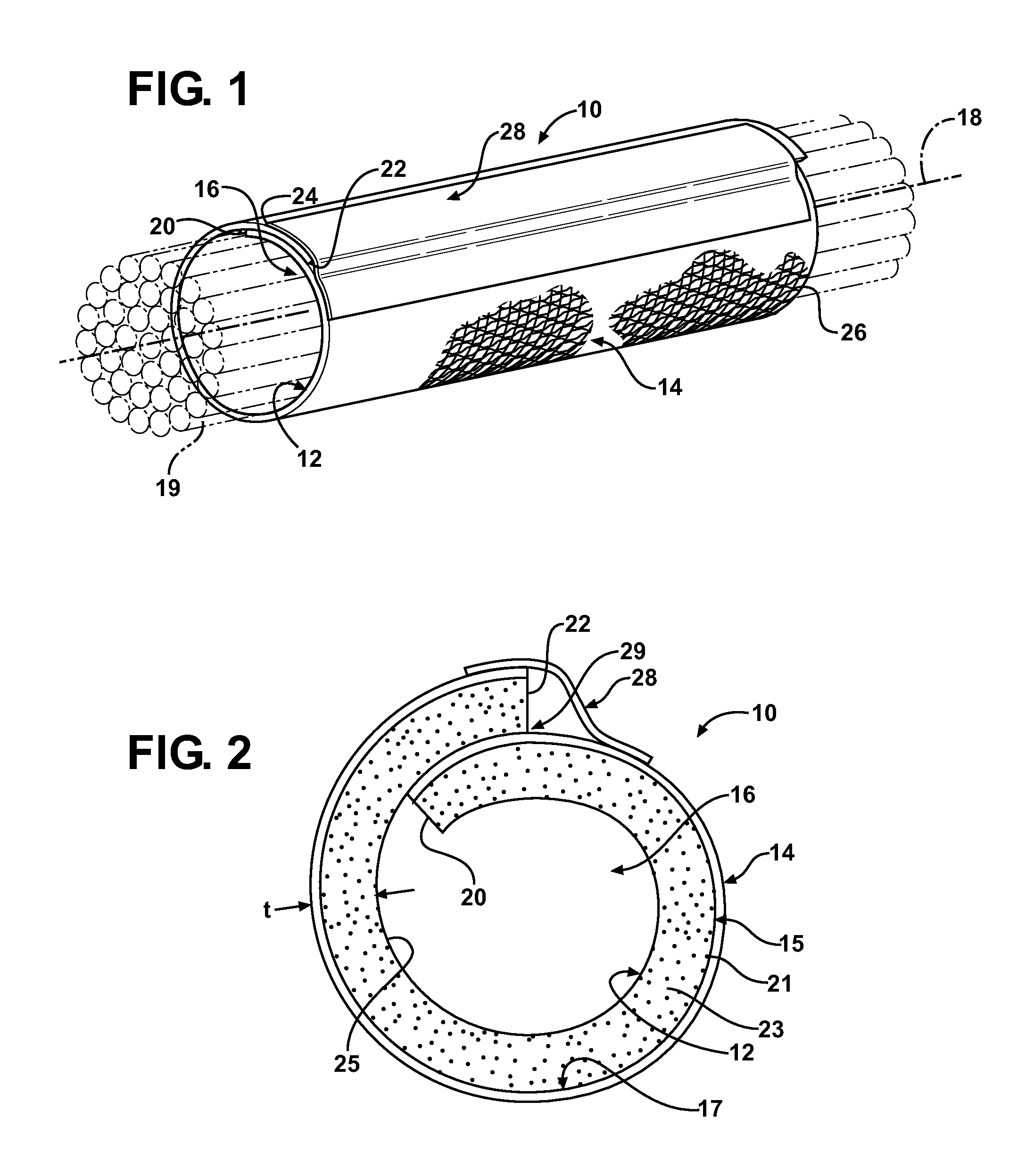
[0021]Referring in more detail to the drawings, FIG. 1 shows a non-woven, self-wrapping thermal sleeve, referred to hereafter as sleeve 10, constructed in accordance with one aspect of the invention. The sleeve 10 has an inner non-woven substrate layer, referred to hereafter as wall 12, constructed from an engineered non-woven material and an outer-most reflective layer 14 applied over an outer surface 15 (FIG. 2) of the wall 12. The wall 12 is heat-set into a self-wrapping tubular configuration to provide an enclosed tubular inner cavity 16 when in its relaxed, self-wrapped configuration. The cavity 16 is readily accessible along a longitudinal axis 18 of the sleeve 10 so that elongate members, such as wires 19 or a wire harness, for example, can be readily disposed radially into the cavity 16, and conversely, removed from the cavity 16, such as during service. The wall 12 can be constructed having any suitable size, including length, diameter and wall thickness, and can also be pr...


PUM

PropertyMeasurementUnit
outer circumferenceaaaaaaaaaa
widthaaaaaaaaaa
forceaaaaaaaaaa

Abstract

A self-wrapping, non-woven sleeve for routing and protecting elongate members includes a non-woven elongate wall having an outer surface with opposite sides extending along a longitudinal axis of the sleeve. The sides self-wrap about the longitudinal axis to provide a tubular cavity in absence of an externally applied force. The sides are extendable away from one another under an externally applied force to expose the cavity for insertion of the elongate members, wherein the sides return to their self-wrapped configuration upon removal of the externally applied force. Further, an outer reflective layer is attached to the outer surface of the self-wrapping wall to provide enhanced thermal protection to the elongate members in the cavity.

Description

CROSS-REFERENCE TO RELATED APPLICATION[0001]This application claims the benefit of U.S. Provisional Application Ser. No. 61 / 060,894, filed Jun. 12, 2008, which is incorporated herein by reference in its entirety.BACKGROUND OF THE INVENTION[0002]1. Technical Field[0003]This invention relates generally to sleeves for protecting elongate members, and more particularly to non-woven, self-wrapping thermal sleeves.[0004]2. Related Art[0005]It is known that wires and wire harnesses carried in sleeves in vehicles, such as in automobiles, aircraft or aerospace craft, can be routed through areas subjected to relatively high heat while in use. As such, it is customary to spirally wrap wires and wire harnesses with high temperature resistant foil tape to reduce the potential for heat damage to the wires. Unfortunately, applying tape is labor intensive, and thus, costly. In addition, the appearance of the tape can be unsightly, particularly over time as the tape wears, which in turn, can result ...

Claims


Application Information

Patent Timeline
Patent Type & Authority Applications(United States)
IPC IPC(8): B32B1/08
CPCB32B5/02F16L59/022B60R16/0215Y10T428/13F16L57/00Y10T428/1362H02G3/0481B32B1/08B32B5/022B32B5/08B32B7/12B32B15/14B32B27/12B32B27/36B32B2255/10B32B2255/205B32B2262/02B32B2262/0253B32B2262/0276B32B2262/12B32B2262/14B32B2307/306B32B2597/00B32B2605/08B32B2605/18
Inventor HARRIS, DAVID A.
Owner FEDERAL MOGUL POWERTAIN LLC
Why Eureka
Try Eureka