Orthopaedic fixation component and method

a technology for orthopaedic surgery and fixation components, applied in the field of orthopaedic fixation components and methods, can solve the problems of loss of fixation and non-union of bone fragments, lack of functionality, and relatively complex procedures, so as to reduce post-operative complications, improve fixation, and improve the effect of fixation

Active Publication Date: 2009-12-17
ECOLE DE TECH SUPERIEURE +1
View PDF13 Cites 60 Cited by
  • Summary
  • Abstract
  • Description
  • Claims
  • Application Information

AI Technical Summary

Benefits of technology

[0018]The proposed orthopaedic fixation component provides a variety of advantages for both the surgeon and the intended patient, some of which are disclosed in greater details at the end of the detailed description portion of the present application. In short, the proposed orthopaedic fixation component is designed so as to improve fixation while reducing post-operative complications.
[0019]The present invention also relates to a method of using an orthopaedic fixation component in order to also improve fixation while reducing post-operative complications.

Problems solved by technology

Also, because of the considerable stress imparted on the greater trochanter as a consequence of the total hip arthroplasty procedure, it is estimated that this type of procedure is associated with a relatively high percentage of greater trochanter post-surgical fractures, which, in turn, may require fixation.
For example, such procedures are typically considered relatively complex.
Furthermore, cable failure, migration or loosening may lead to fixation loss and non-union of the bone fragments with clinical consequences such as pain, lack of functionality and the like.
Again, although somewhat useful, such devices also suffer from numerous drawbacks.
Because it is the most lateral point of the hip region, the greater trochanter may cause discomforts when lateral pressure is exerted on the side of the body such as when an individual lies on his or her side on a hard surface.
Most prior art fixation plates increase the discomfort by being located over the most prominent portion of the greater trochanter.
Also, some prior art devices require that relatively large incisions be performed in large leg muscles to position them properly over the greater trochanter, with all the discomfort and risk for complications associated with such operations.

Method used


Image

  • Orthopaedic fixation component and method
  • Orthopaedic fixation component and method
  • Orthopaedic fixation component and method

Examples


Embodiment Construction

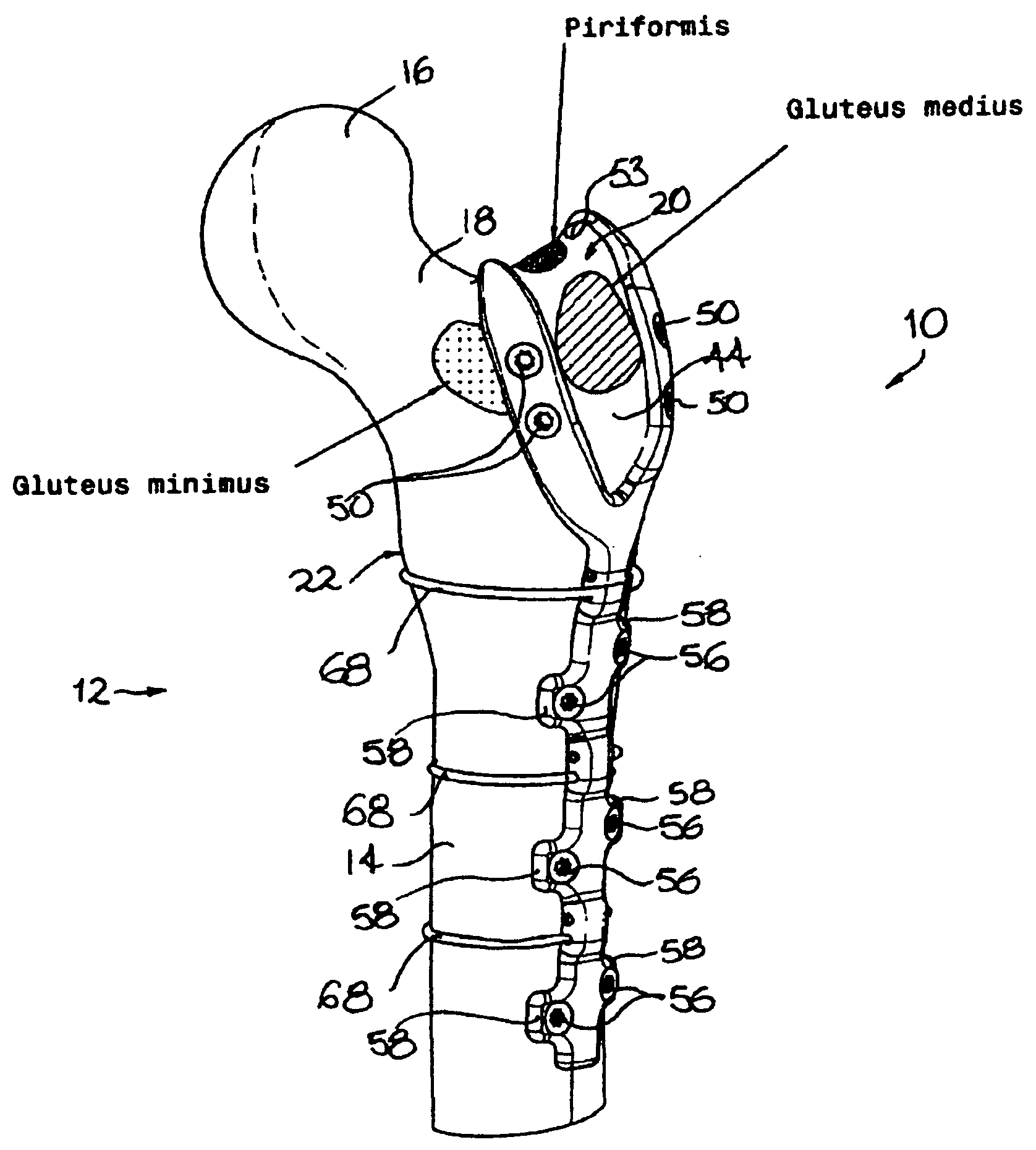
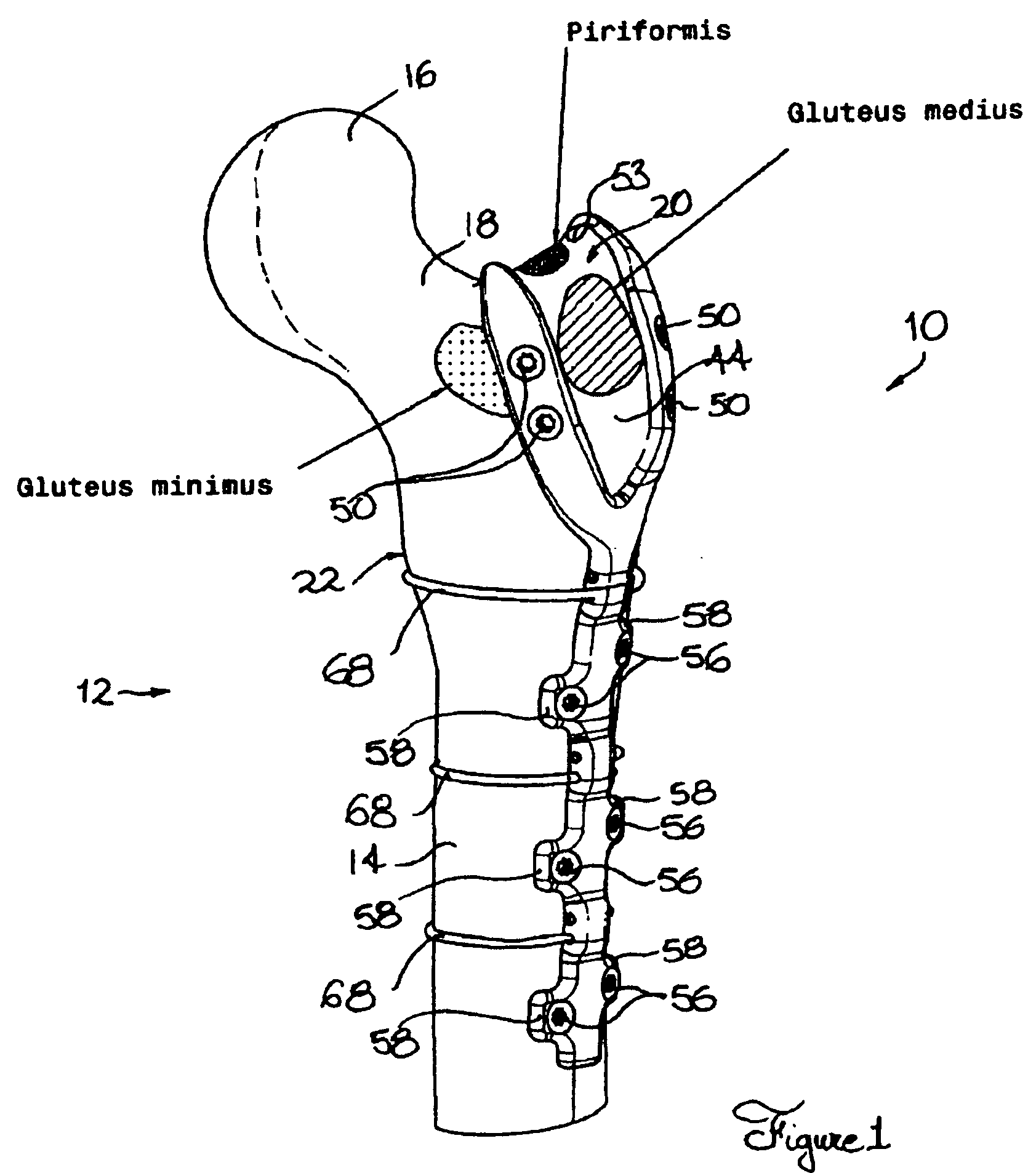
[0031]Referring to FIG. 1, there is shown, in a perspective view, a fixation component in accordance with an embodiment of the present invention, generally indicated by the reference numeral 10. The fixation component 10 is shown, by way of example, mounted to a femur generally indicated by reference numeral 12. It should, however, be understood that the fixation component 10 is only shown mounted to a femur 12 by way of example and that the fixation component 10 could be used for fixating or securing bone segments located at other anatomical regions without departing from the present invention.

[0032]More specifically, the fixation component 10 is particularly well adapted to be used at anatomical regions involving substantially elongated bones defining a corresponding bone end region. By way of non limitative examples, the fixation component 10 could, for example, be used in applications involving the distal femur, the proximal tibia as well as the proximal and distal humerus regio...


PUM


Abstract

An orthopaedic fixation component attachable to a femur, said femur defining a femur shaft, a femur head and a femur neck extending therebetween, said femur further defining a greater trochanter limiting laterally said femur neck, said orthopaedic fixation component comprising: a shaft section fixation portion and an end section fixation portion extending substantially longitudinally therefrom, said shaft section and end section fixation portions being respectively securable to said femur shaft and said greater trochanter; said end section fixation portion including a pair of end arms, said end arms being configured, sized and positioned to delimit a trochanter receiving recess for substantially fittingly receiving a prominent portion of said greater trochanter.

Description

[0001]The present application claims priority from U.S. Provisional Patent Application Ser. No. 61 / 129,221 filed on Jun. 12, 2008.FIELD OF THE INVENTION[0002]The present invention relates to the general field of orthopaedic surgery components and methods and is particularly concerned with an orthopaedic fixation component and method.BACKGROUND[0003]There exists a wide variety of situations wherein it is desirable to fixate adjacent bone pieces or segments to promote healing of a fracture. Such situations occur, for example, whenever a fragment of the greater trochanteric portion of the femur bone needs to be fixated to the shaft of the femur.[0004]With the aging demographics of many industrialized countries, hip related surgical procedures are becoming increasingly prevalent. An example of such procedures is the so-called total hip replacement surgery or arthroplasty which is typically performed as a consequence of osteoarthritis of the hip joint. The procedure involves replacing th...

Claims


Application Information

Patent Timeline
Patent Type & Authority Applications(United States)
IPC IPC(8): A61B17/56
CPCA61B17/74A61B17/809A61B17/8061A61B2017/00867A61B17/82
Inventor PETIT, YVANLAFLAMME, GEORGES YVESBOURGEOIS, YAN
Owner ECOLE DE TECH SUPERIEURE
Why Eureka
Try Eureka