Method and Device for Electrokinetic Manipulation

Inactive Publication Date: 2009-12-24
TECHNION RES & DEV FOUND LTD
View PDF4 Cites 29 Cited by
  • Summary
  • Abstract
  • Description
  • Claims
  • Application Information

AI Technical Summary

Benefits of technology

[0017]According to further features in preferred embodiments of the invention described below, the electrically floating electrode structure(s) is designed and configured to control non-uniformities in the electric field.
[0018]According to still further features in the described preferred embodiments the electrically floating electrode structure(s) is designed and configured to increase non-uniformities in the electric field.
[0019]According to an additional aspect of the present invention there is provided a method of fabricating a device for manipulating an object by electrokinetics. The method compr

Problems solved by technology

This results in nonuniform electric fields.
It is generally difficult to manufacture dielectrophoretic devices, inter alia due to the need to establish electrical contact between the microelectrodes generating the nonuniform field and the external power

Method used


Image

  • Method and Device for Electrokinetic Manipulation
  • Method and Device for Electrokinetic Manipulation
  • Method and Device for Electrokinetic Manipulation

Examples


example 1

Mathematical Formulae

[0116]A particle subjected to a nonuniform electric field ({tilde under (E)}) experiences polarization. The electric force ({tilde under (F)}elect) acting upon the particle is a function of the field distribution and the dielectric polarization components induced in the particle by the field. If the particle is neutral or an alternating field whose time average is zero is applied, the electric force resulting from net charge vanishes. In this case, the dipolar moment induced in the particle and the field gradient values dominate the electric force. The resulting force can be approximated as:

{tilde under (F)}elect=2π∈mR3[Re{fCM}∇{tilde under (E)}rms2+Im{fCM}(Ex2∇φx+Ey2∇φy+Ez2∇φz)],  (EQ. 1)

where is the time averaged value of x, ∈m is the medium permittivity, R is the particle radius, Re{x} and Im{x} are the real and imaginary components of x respectively, ∇ is the gradient operator, {tilde under (E)}rms is the root mean square electric field, Ei is the electric ...

example 2

Simulations

[0123]Computer simulations of the electrical field within two types of model devices were performed.

Methods

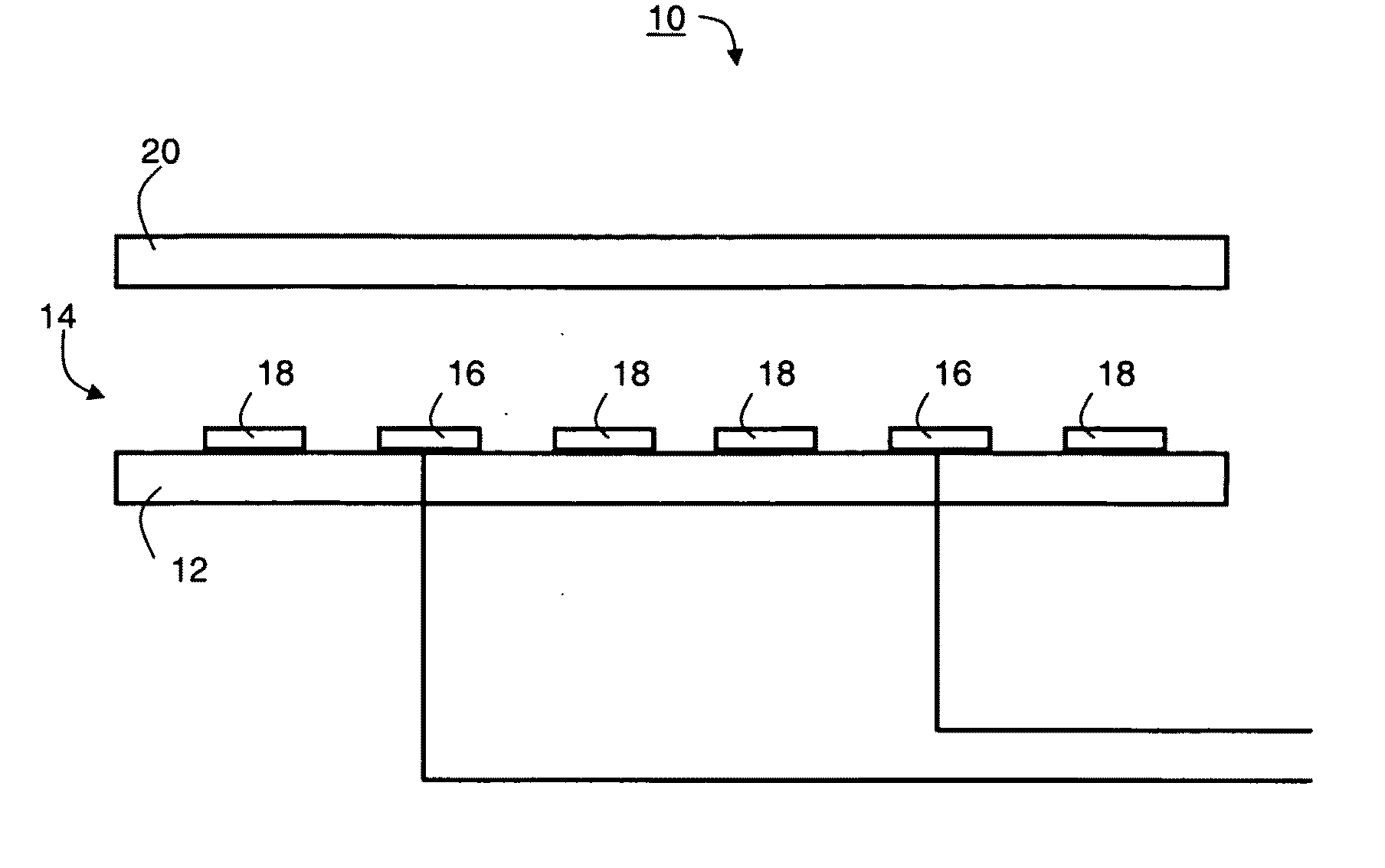
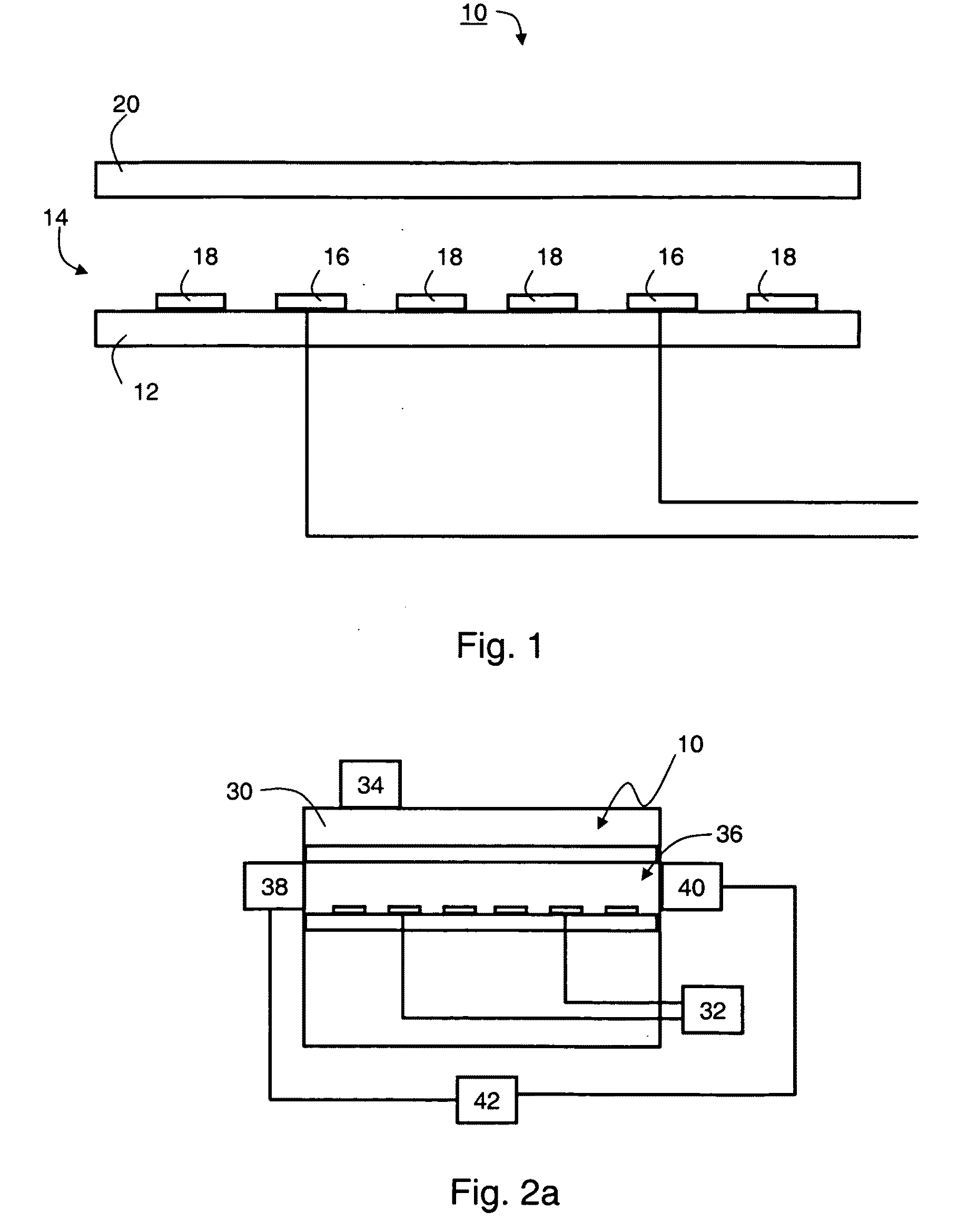
[0124]The model devices are schematically illustrated in FIGS. 5a-d. A first model device, illustrated in FIGS. 5a (top view) and 5b (fragmentary side view) was designed according to a preferred embodiment of the present invention and included both electrically biasable electrode structures and electrically floating electrode structures. The electrically biasable electrode structures were arranged in an interdigitated arrangement.

[0125]As illustrated in FIG. 5a, the electrically biasable electrode structures comprise first electrode stem 52, disposed proximate to the substrate surface 56 and parallel with a second electrode stem 54, proximate to the same surface. The first electrode stem is connected to a first terminal of an AC power source 58, and the second electrode stem is connected to a second terminal of power source 58, such that that the first electrode stem...

example 3

Prototype Device

[0147]A prototype device was manufactured in accordance with preferred embodiments of the present invention. The prototype device was used for manipulating erythrocytes in blood sample.

Materials and Methods

[0148]Two different electrode configurations were fabricated. The two electrode configurations had different feature sizes and were fabricated using different processes and materials.

[0149]In a first configuration, each electrode was 12.5 μm in width, and adjacent electrodes were separated by a 12.5 μm gap. A 200-Å-thick titanium and a 2000-Å-thick gold layers were subsequently deposited on a microscope slide using an electron-beam evaporator. The Ti / Au electrodes were obtained using a lift-off process. The obtained device included various electrode layouts in an arrangement in which 7-8 floating electrodes were located between or adjacent to two biasable electrodes. The number of the floating electrodes and their arrangement in relation to the biased electrodes wa...


PUM


Abstract

A device for manipulating an object present in a fluid by electrokinetics is disclosed. The device comprises a substrate forming a flow chamber. The device further comprises a plurality of electrically biasable electrode structures and at least one electrically floating electrode structure.

Description

FIELD AND BACKGROUND OF THE INVENTION[0001]The present invention relates to object manipulation and, more particularly to a method and device for manipulating small scale objects by electrokinetics.[0002]Electrokinetics is the use of electrical fields (and the resulting forces) to manipulate matter in a fluid medium. Electrokinetics is a term which encompasses all types of processes in which the application of electric field results in motion of matter.[0003]One type of electrokinetics is electrophoresis. Electrophoresis is a phenomenon in which charged particles, located between two electrically biased electrodes, are influenced by the electric field generated by the electrodes such that they are attracted to one electrode and repulsed by the other electrode. The attracting and repulsing forces are proportional to the particle net charge and the electric field magnitude.[0004]Another type of electrokinetics is dielectrophoresis. Dielectrophoresis is the motion of matter caused by p...

Claims


Application Information

Patent Timeline
IPC IPC(8): B01D57/02B05D5/12
CPCB01F13/0076B01L3/502738B01L3/502761B01L2200/0647B01L2200/12B01L2300/0636C12M47/04B01L2300/0877B01L2400/0415B01L2400/0424B01L2400/0496B03C5/026B03C5/028B01L2300/0819B01F33/3031
Inventor GOLAN, SAARDINNAR, URIELATA, DAVIDORENSTEIN, MEIR
Owner TECHNION RES & DEV FOUND LTD
Why Eureka
Try Eureka