Fiber optic cable having armor with easy access features

a fiber optic cable and armor technology, applied in the field of fiber optic cable designs, can solve the problems of slow acceptance of tubeless designs in the market, difficulty and time-consuming for craftsmen, and inability to exercise care by craftsmen, so as to reduce the risk of damaging the optical fiber and facilitate and safe access

Inactive Publication Date: 2009-12-24
CORNING CABLE SYST LLC
View PDF4 Cites 117 Cited by
  • Summary
  • Abstract
  • Description
  • Claims
  • Application Information

AI Technical Summary

Benefits of technology

[0008]The present disclosure is generally directed to a fiber optic cable including a cable core and an armor surrounding the cable core. The cable core has at least one optical fiber and the armor includes one or more lines of scoring extending along...

Problems solved by technology

It can be difficult and time consuming for the craft to remove the armor to access the optical fibers within the fiber optic cable.
Additionally, injury can result if the craftsman does not exercise care when opening the armor to access the optical fibers.
Consequently, tubeless designs have been slow to gain accep...

Method used


Image

  • Fiber optic cable having armor with easy access features
  • Fiber optic cable having armor with easy access features
  • Fiber optic cable having armor with easy access features

Examples


Embodiment Construction

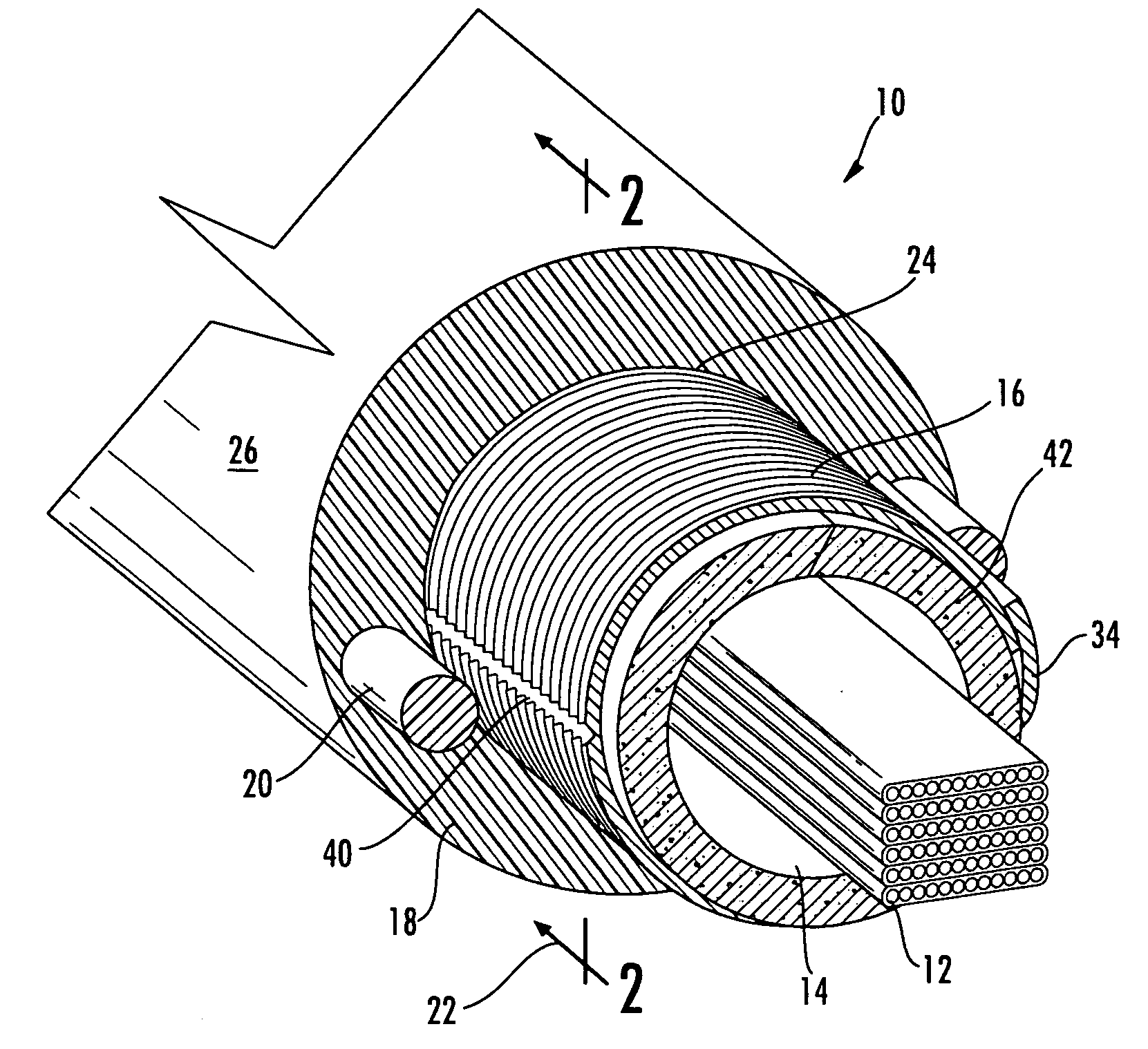
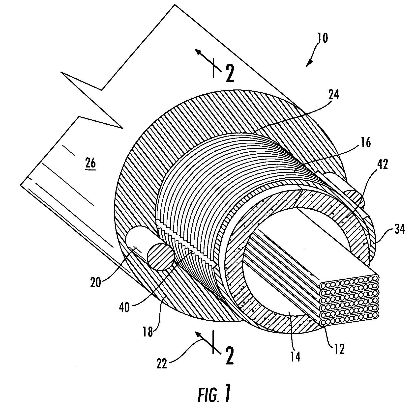
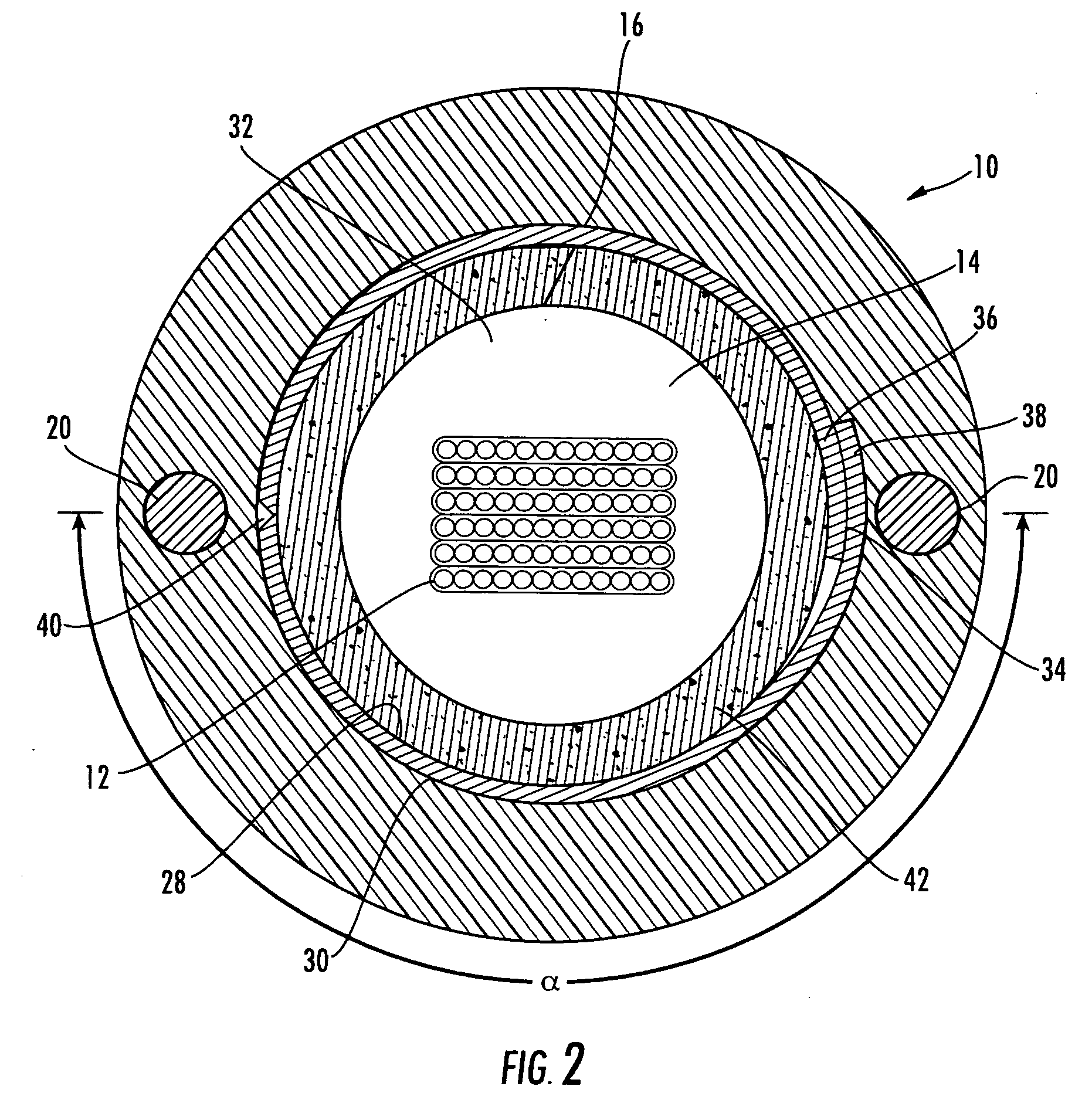
[0023]Reference will now be made in detail to the preferred embodiments of the present invention, examples of which are illustrated in the accompanying drawings. Whenever possible, like reference numbers will be used to refer to like components or parts. Examples of fiber optic cables according to various aspects of the present invention are disclosed in the figures, as described below. The various disclosed aspects of the embodiments below may be combined or modified to create further embodiments of the invention.

[0024]FIGS. 1 and 2 depict a first example of a fiber optic cable 10 including at least one optical fiber 12 generally disposed within a cavity 14 of an armor 16 that extends in a substantially longitudinal direction. Fiber optic cable 10 can also include a cable jacket 18 and / or at least one strength member 20. As depicted, fiber optic cable 10 is a tubeless configuration, meaning that the optical fibers are disposed in an outer cable jacket, but no buffer tube is dispose...


PUM


Abstract

The present disclosure is generally directed to a fiber optic cable including a cable core and an armor surrounding the cable core. The cable core has at least one optical fiber and the armor includes one or more lines of scoring extending along a longitudinal length of the armor, thereby creating a dedicated location for the craft to open the armor to access the cable core and optical fibers therein.

Description

BACKGROUND OF THE INVENTION[0001]1. Field of the Invention[0002]The present invention relates generally to fiber optic cable designs that include features for opening the armor of the cables, thereby allowing the craftsman quick and easy access to the optical fibers within the cable.[0003]2. Technical Background[0004]Fiber optic cables are used to transmit data in indoor and outdoor environments. Various types of fiber optic cable designs have been proposed. For example, outdoor long-haul applications can use loose-tube cables in which one or more optical fibers are disposed within a plastic buffer tube that can be filled with a thixotropic material such as a grease or gel. Buffer tubes for outdoor cables can serve several functions such as protecting the optical fiber(s) therein along with segregating and grouping the optical fiber(s). Generally speaking, outdoor cables are robust designs intended to protect the optical fibers.[0005]It is common for outdoor cables to include an arm...

Claims


Application Information

Patent Timeline
IPC IPC(8): G02B6/44
CPCG02B6/443G02B6/4495G02B6/4432G02B6/4431
Inventor BLAZER, BRADLEY J.GIMBLET, MICHAEL J.GREENWOOD III, JULIAN L.HENKEL, JOSEPH N.ROBERTS, REGINALD
Owner CORNING CABLE SYST LLC
Why Eureka
Try Eureka