This helps you quickly interpret patents by identifying the three key elements:
Problems solved by technology
Method used
Benefits of technology
Benefits of technology
[0012]The image forming apparatus of the invention can prevent unnecessary rotation of motors and hence maximize the life of components to be driven by the motors.
This case however may cause a disadvantage that a wait time is long from power-on until image formation becomes ready to start.
Method used
Image
Click on the blue label to locate the original text in one second.
Reading with bidirectional positioning of images and text.
Examples
embodiment 1
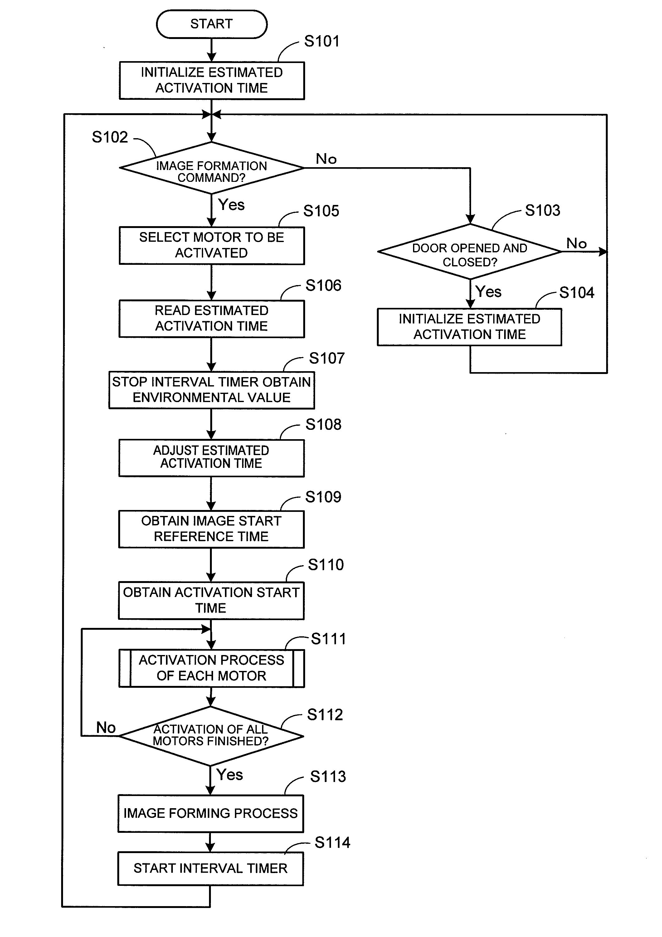
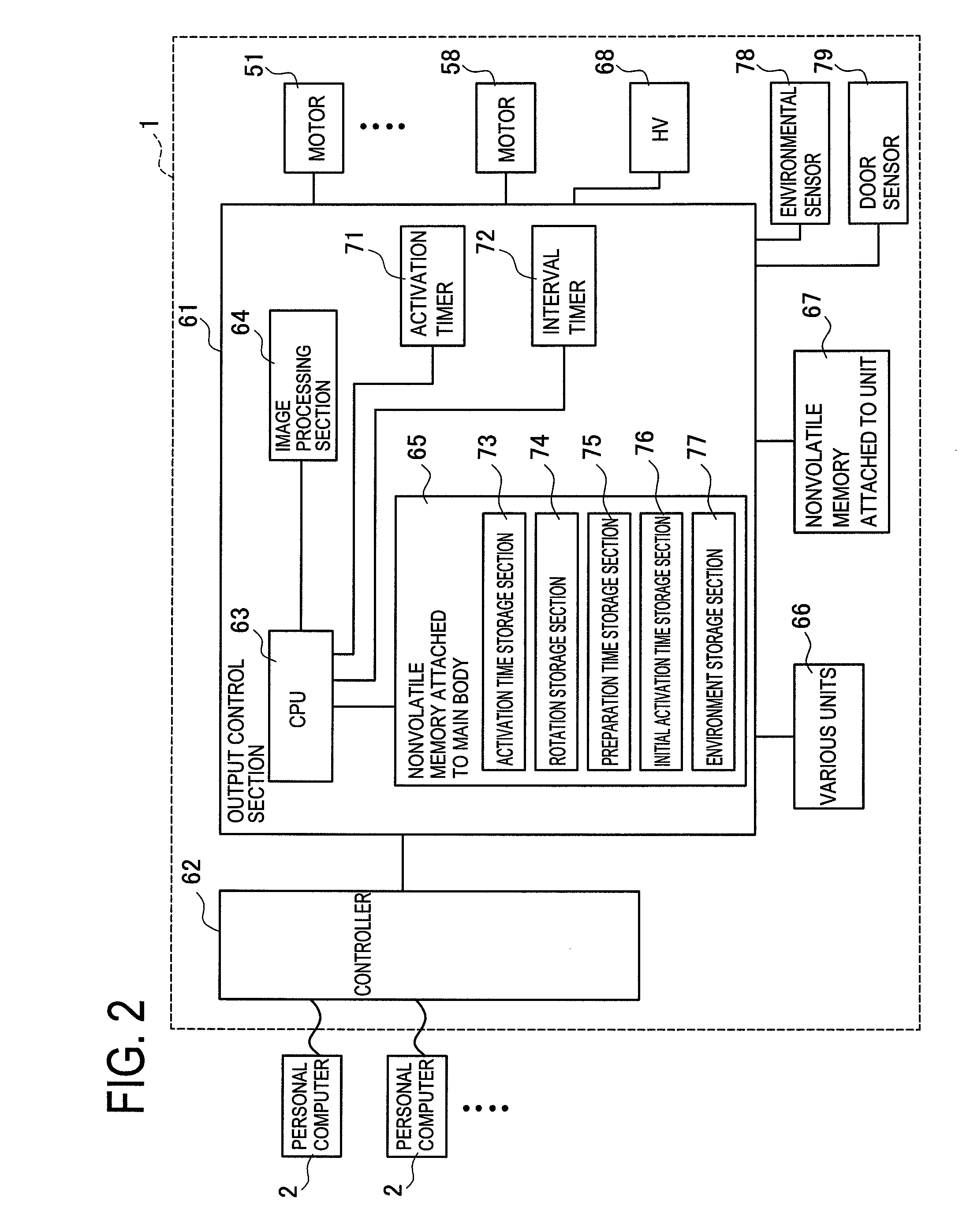
[0022]A detailed description of a preferred embodiment of an electrophotographic image forming apparatus embodying the present invention will now be given referring to the accompanying drawings.
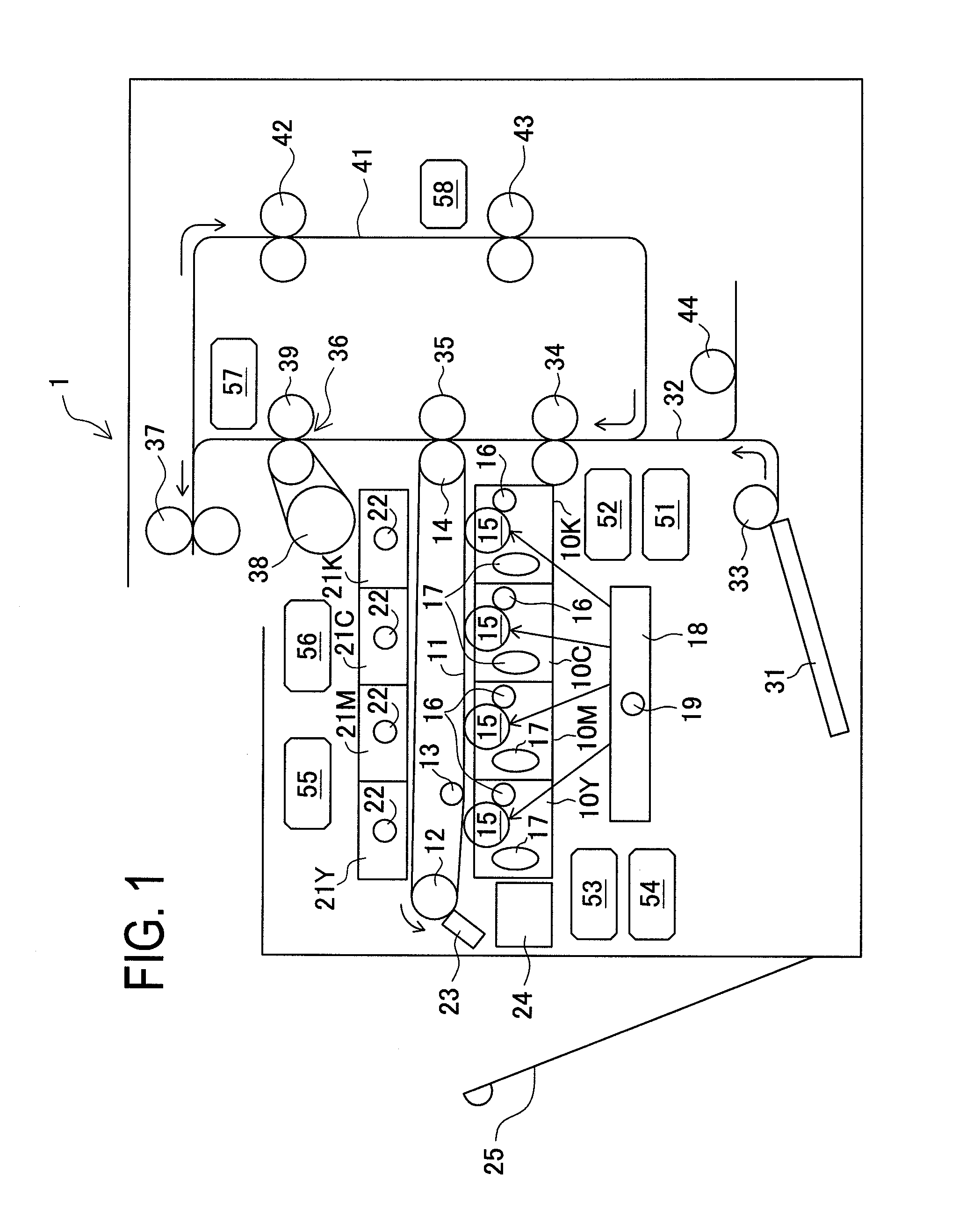
[0023]FIG. 1 shows a schematic configuration of a color printer 1 of this embodiment. This is a so-called tandem printer in which various color image cartridges 10Y, 10M, 10C, and 10K are arranged along an intermediate transfer belt 11. The intermediate transfer belt 11 is wound over three rollers 12, 13, and 14 and driven by them to rotate. Each of the image cartridges 10Y, 10M, 10C, and 10K includes a photoconductor 15, a charger 16, and a developer 17. Under the image cartridges 10Y, 10M, 10C, and 10K, an exposure 18 is disposed in which a polygon mirror 19 is placed.
[0024]Above the intermediate transfer belt 11 in FIG. 1, toner bottles 21Y, 21M, 21C, and 21K each containing each color toner are arranged. In each of the toner bottles 21Y, 21M, 21C, and 21K, an agitating blade 22 is provide...
embodiment 2
[0083]Another embodiment of the invention will be explained in detail below with reference to the accompanying drawings. This embodiment is identical in mechanical configuration to the first embodiment excepting a setting method of the estimated activation times.
[0084]The image forming process in the color printer of this embodiment is explained below referring to a flowchart of FIG. 7. In this embodiment, similarly, upon power-on, values in the activation time storage section 73 are first initialized (S301). If the door 25 is opened and closed (S303: Yes), those values are also initialized (S304). The flow waits until an image forming command is received (S302: No).
[0085]Upon receipt of the image forming command (S302: Yes), the motor(s) to be activated is(are) selected (S305). Subsequently, the estimated activation time(s) of the motor(s) to be activated is(are) read (S306). The interval timer 72 is then stopped and a detection result of the environmental sensor 78 is obtained (S3...
PUM
Abstract
A color printer of the invention is controlled to select DC motors needed to be newly activated according to a print mode when a print job occurs, determine an activation start time of each selected DC motor by sequentially going back activation times stored in relation to the selected DC motors from an image start reference time, activate one or ones of the DC motors to be activated according to the determined activation start times, measure an actual activation time of the activated DC motor and update a stored content about the activation time based on a measurement result of the actual activation time, and determine an activation start time of each DC motor based on the updated activation time. An image forming apparatus capable of preventing the motors from rotating more than necessary and effectively utilizing the life of components to be driven by the motors can be provided.
Description
[0001]This application is based upon and claims the benefit of priority from the prior Japanese Patent Application No. 2008-159904 filed on Jun. 19, 2008, the entire contents of which are incorporated herein by reference.TECHNICAL FIELD[0002]The present invention relates to an image forming apparatus having a DC motor and, more particularly, to an image forming apparatus having a plurality of DC motors whereby corresponding load devices are respectively driven to rotate.BACKGROUND ART[0003]Image forming apparatuses each have a plurality of rotary bodies such as a photoconductor and developing roller. Most of the apparatuses also include a plurality of motors for rotating the rotation bodies respectively. For instance, during activation by power-on, some of inactive motors need to be activated individually and controlled to rotate at respective required rotation speeds. However, during motor activation, a larger amount of electric current generally has to be supplied as compared with...
Claims
Application Information
Patent Timeline
Application Date:The date an application was filed.
Publication Date:The date a patent or application was officially published.
First Publication Date:The earliest publication date of a patent with the same application number.
Issue Date:Publication date of the patent grant document.
PCT Entry Date:The Entry date of PCT National Phase.
Estimated Expiry Date:The statutory expiry date of a patent right according to the Patent Law, and it is the longest term of protection that the patent right can achieve without the termination of the patent right due to other reasons(Term extension factor has been taken into account ).
Invalid Date:Actual expiry date is based on effective date or publication date of legal transaction data of invalid patent.

