Motor controller, conveyor, image forming apparatus, and motor control method

a technology of motor controller and image forming apparatus, which is applied in the direction of dynamo-electric converter control, motor/generator/converter stopper, dynamo-electric gear control, etc., can solve the problem of winding generating heat during stop, motor will not normally operate, and sharp decrease in inductance, so as to prevent unnecessary rotation and suppress heat generation of motors

Active Publication Date: 2020-08-04
KONICA MINOLTA INC
View PDF5 Cites 2 Cited by
  • Summary
  • Abstract
  • Description
  • Claims
  • Application Information

AI Technical Summary

Benefits of technology

[0015]The present invention has been made in view of the problem described above, and an object of the present invention is to provide a controller and a control method capable of suppressing heat generation of a motor during the stop and preventing unnecessary rotation due to an expected disturbance torque.

Problems solved by technology

However, since a fixed excitation current (hold current) for holding the rotor is continuously caused to flow through the winding, there is a problem that the winding generates heat during stop.
If the amount of heat generation exceeds a limit temperature in a specification of the winding, degradation and breakage of coating material (resin or the like) of the winding, disappearance of magnetic action (sharp decrease in inductance), and the like occur, and there is a possibility that the motor will not normally operate.
Since the techniques of JP 2011-182505 A and JP 2017-158354 A described above relate to the brushless motor but do not relate to control during a period in which the rotation is stopped, it is not possible to solve the problem of heat generation during the stop described above.

Method used


Image

  • Motor controller, conveyor, image forming apparatus, and motor control method
  • Motor controller, conveyor, image forming apparatus, and motor control method
  • Motor controller, conveyor, image forming apparatus, and motor control method

Examples


Embodiment Construction

[0029]Hereinafter, one or more embodiments of the present invention will be described with reference to the drawings. However, the scope of the invention is not limited to the disclosed embodiments.

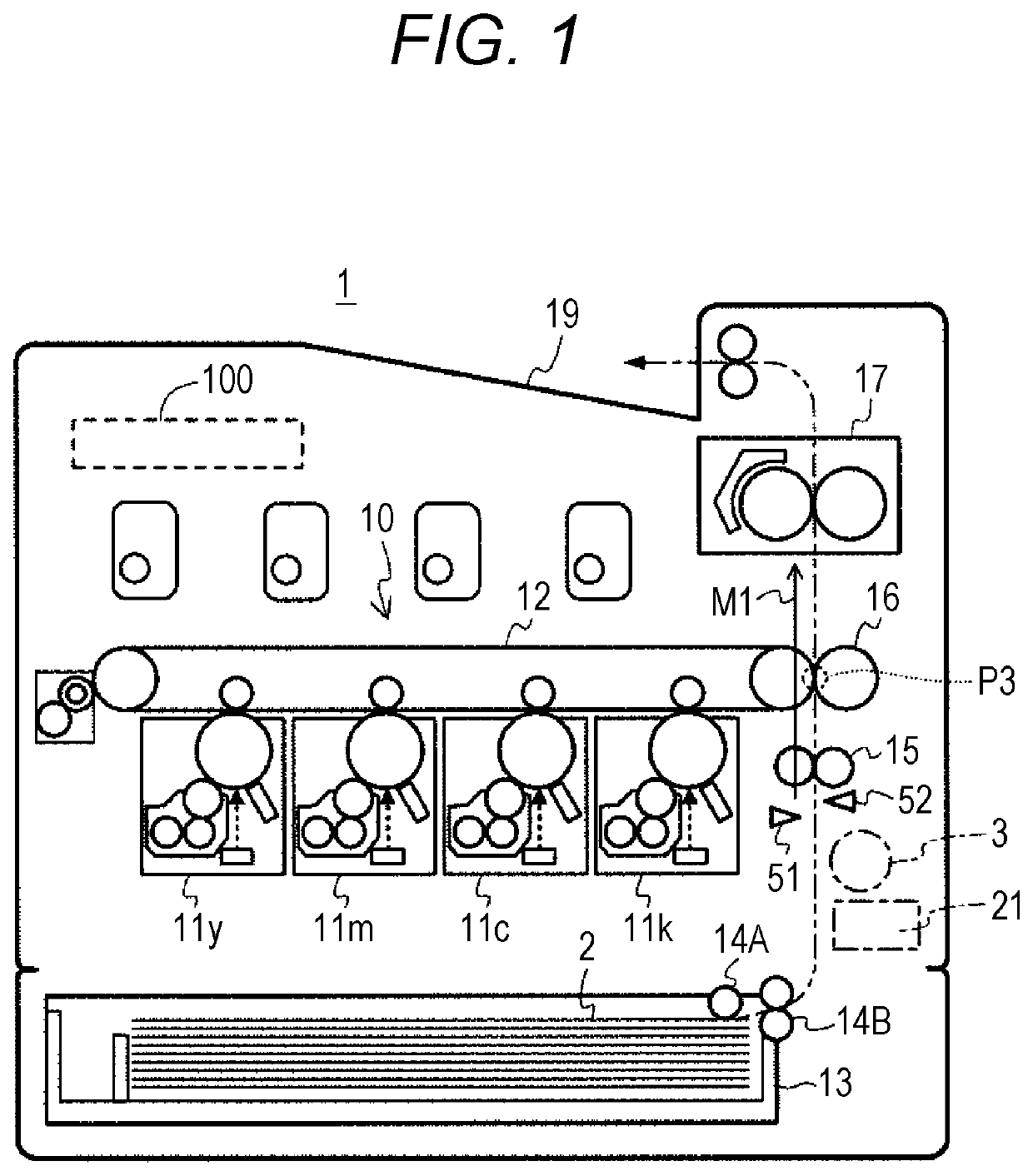
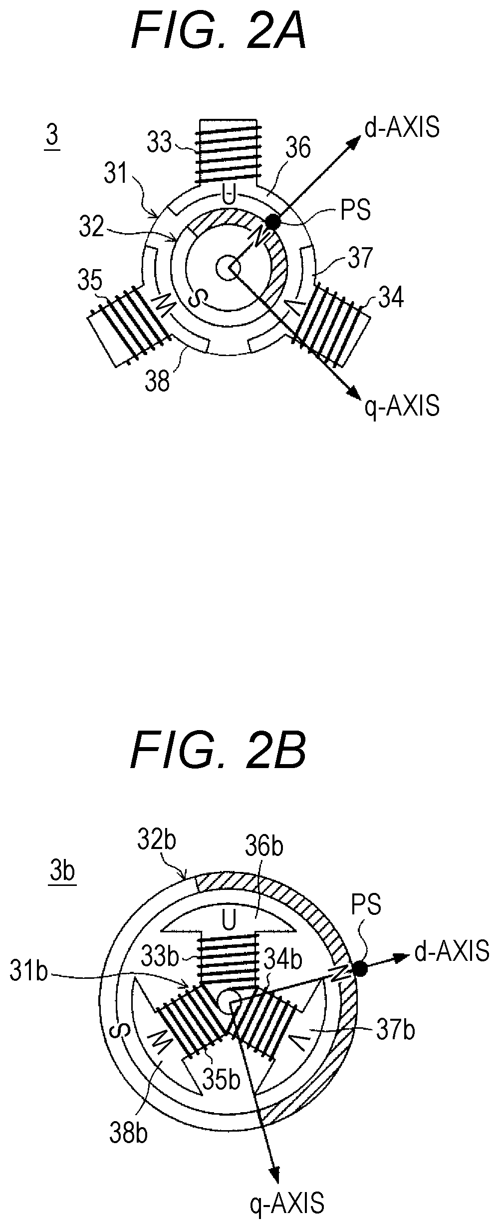
[0030]FIG. 1 illustrates an outline of a configuration of an image forming apparatus 1 including a motor controller 21 according to an embodiment of the present invention, and FIGS. 2A and 2B each schematically illustrate a configuration of a motor 3.

[0031]In FIG. 1, the image forming apparatus 1 is an electrophotographic color printer including a tandem type printer engine 10. The image forming apparatus 1 forms a color or monochrome image depending on a job input from an external host apparatus via a network. The image forming apparatus 1 includes a control circuit 100 that controls operation of the image forming apparatus 1. The control circuit 100 includes a processor that executes a control program and peripheral devices (ROM, RAM, and the like) of the processor.

[0032]The printer eng...


PUM


Abstract

A motor controller that controls a motor in which a rotor using a permanent magnet is rotated by a rotating magnetic field due to a current flowing through a winding: performs hold control that continuously causes a fixed excitation current to flow through the winding to cause a fixed magnetic field for suppressing rotation of the rotor to be generated in a suspension period in which the motor is stopped; performs hold enhancement control that enhances the fixed magnetic field with input of a timing signal defined in advance as a trigger, in the suspension period; and starts rotational excitation control that generates the rotating magnetic field when a rotation start timing arrives.

Description

[0001]The entire disclosure of Japanese patent Application No. 2018-087982, filed on May 1, 2018, is incorporated herein by reference in its entirety.BACKGROUNDTechnological Field[0002]The present invention relates to a motor controller, a conveyor, an image forming apparatus, and a motor control method.Description of the Related Art[0003]An image forming apparatus such as a printer, a copying machine, or a multifunction machine takes out a sheet (recording sheet) from a storing unit and conveys the sheet, and prints an image on the sheet being conveyed at a predetermined position. In a conveyance path inside the image forming apparatus, rollers are arranged at intervals shorter than the length of the sheet, and the image forming apparatus controls rotational driving of the rollers so that the sheet passes through each position on the conveyance path at a predetermined timing.[0004]In recent years, in drive sources that rotate the rollers, power saving is progressing by replacement ...

Claims


Application Information

Patent Timeline
Patent Type & Authority Patents(United States)
IPC IPC(8): H02P21/26H02P21/18H02P21/22G03G15/00
CPCH02P21/18H02P21/26H02P21/22G03G15/6558G03G2215/00945G03G2215/00679B41J11/00B41J13/0009B41J13/02H02P6/15H02P6/18H02P21/24H02P27/08H02P2205/01H02P3/025
Inventor FUJIMORI, HARUMITSUKOBAYASHI, YUJIYOSHIDA, KAZUMICHI
Owner KONICA MINOLTA INC
Why Eureka
Try Eureka