Lithium secondary battery

Inactive Publication Date: 2009-04-23
PANASONIC CORP
View PDF6 Cites 26 Cited by
  • Summary
  • Abstract
  • Description
  • Claims
  • Application Information

AI Technical Summary

Benefits of technology

[0009]The lithium secondary battery of the invention includes: a positive electrode including a positive electrode active material; a negative electrode including a negative electrode active material; a separator; and a non-aqueous electrolyte. The negative electrode acti

Problems solved by technology

However, portable small-size electronic devices are required to provide more functions and thus longer continuous operation time.
However, in order to put lithium secondary batteries including alloy-type negative electrode active materials into practical use, there are some problems to be solved.
A large change in the volume of an active material due to charge/discharge causes, for example, a poor contact between the active material and the current collector, thereby resulting in shortened charge/discharge cycle life.
W

Method used


Image

  • Lithium secondary battery
  • Lithium secondary battery
  • Lithium secondary battery

Examples


example 1

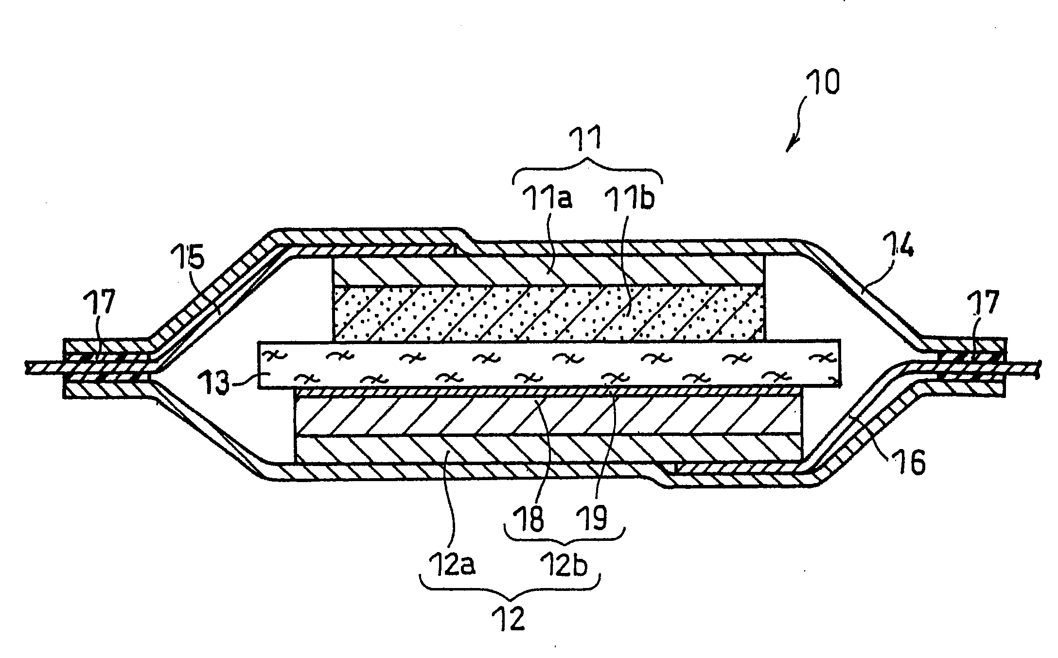
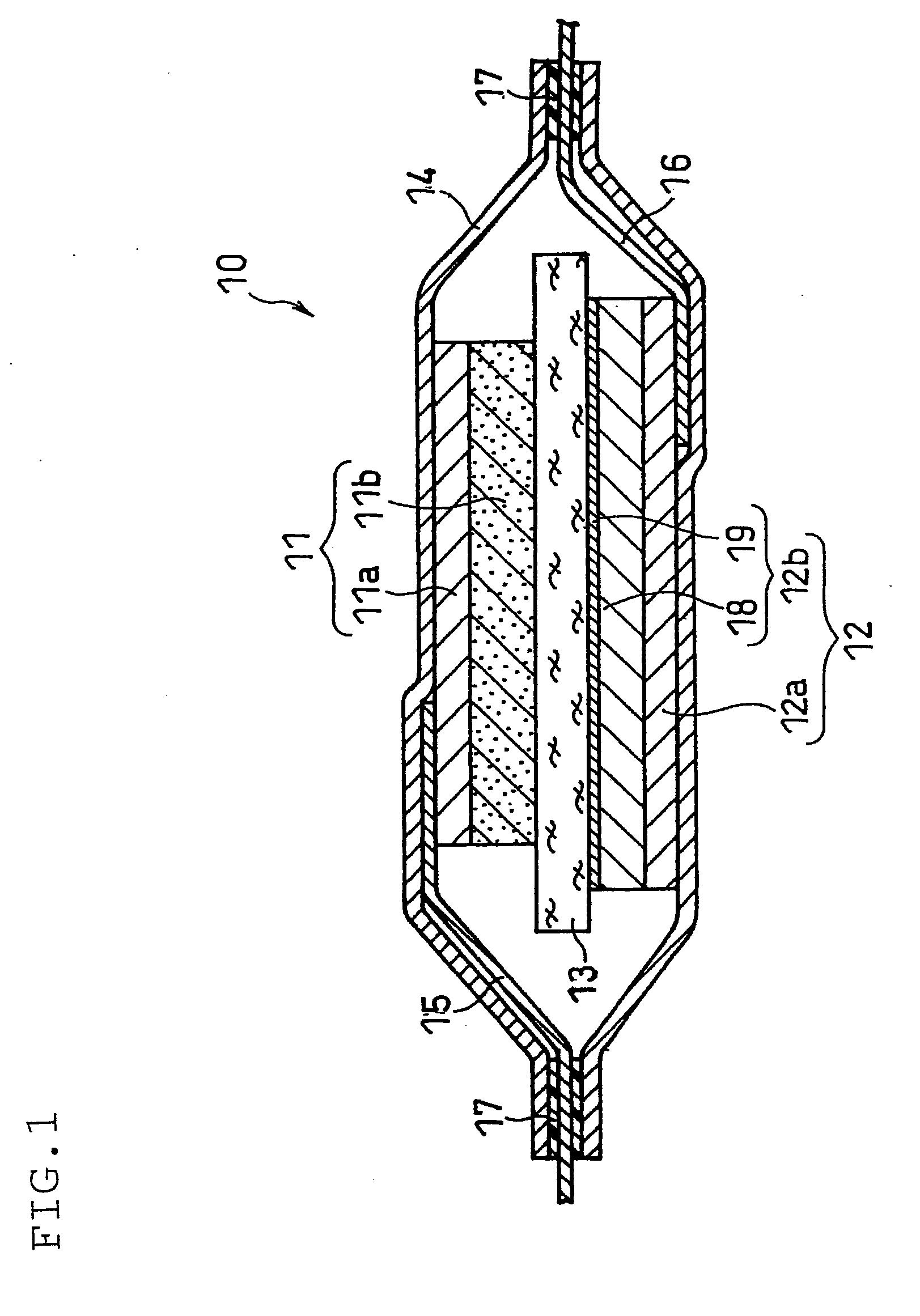
[0140]A lithium secondary battery as illustrated in FIG. 1 was produced.

(i) Preparation of Positive Electrode

[0141]A positive electrode mixture paste was prepared by sufficiently mixing 10 g of lithium nickelate (LiNiO2) powder with a mean particle size of 5 μm, serving as the positive electrode active material, 0.4 g of acetylene black, serving as the conductive agent, 0.3 g of polyvinylidene fluoride, serving as the binder, and a suitable amount of N-methyl-2-pyrrolidone (NMP).

[0142]The paste was applied onto one face of a 15-μm thick positive electrode current collector made of aluminum foil, dried and rolled to form a positive electrode active material layer. The positive electrode sheet thus obtained was cut to a predetermined shape to obtain a positive electrode. The positive electrode active material layer carried on one face of the current collector had a thickness of 60 μm and a size of 30 mm×30 mm. One end of an aluminum positive electrode lead was connected to the face of...

example 2

[0151]A battery of Example 2 was produced in the same manner as in Example 1, except that a second portion (surface layer) comprising carbon was formed by using a carbon deposition device (VC-100 available from Vacuum Device Inc.).

[0152]Specifically, a current collector with a SiO0.5 layer formed thereon was placed in the vacuum chamber of the carbon deposition device. A mechanical pencil lead with a diameter of 0.5 mm was placed so that it faced the SiO0.5 layer of the current collector. By passing a current until the mechanical pencil lead was burned out, a carbon layer with a thickness of approximately 30 nm was formed on the SiO0.5 layer. This operation was repeated 66 times, so that a carbon layer with a thickness of approximately 2 μm was formed.

example 3

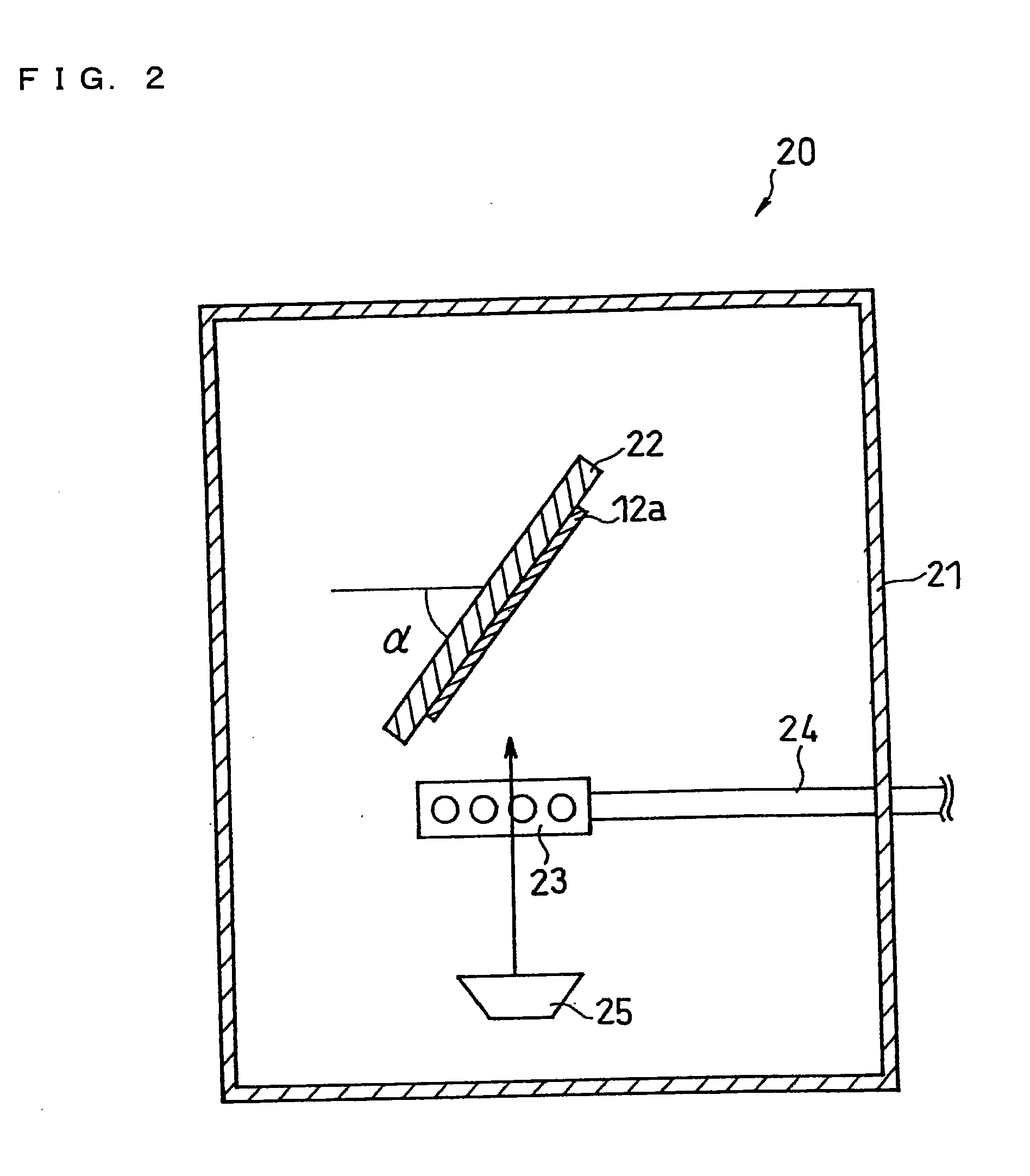
[0153]A battery of Example 3 was produced in the same manner as in Example 1 except that a surface layer comprising SiO1.3 was formed. The SiO1.3 surface layer was formed basically in the same manner as the SiO0.5 layer, but the flow rate of oxygen gas from the nozzle 23 was set to 80 sccm. The acceleration voltage of the electron beam applied to the target 25 was set to −8 kV, and the emission was set to 200 mA.


PUM


Abstract

A lithium secondary battery of this invention includes: a positive electrode including a positive electrode active material; a negative electrode including a negative electrode active material; a separator; and a non-aqueous electrolyte. The negative electrode active material includes a first portion capable of absorbing and desorbing lithium ions and a second portion covering at least a part of a surface of the first portion. The second portion includes at least one material that is less reactive with oxygen than the first portion.

Description

FIELD OF THE INVENTION[0001]The invention relates to lithium secondary batteries, and mainly to an improvement of a negative electrode included in a lithium secondary battery.BACKGROUND OF THE INVENTION[0002]Lithium secondary batteries have high capacity and high energy density, and their size and weight can be easily reduced. They are thus widely used as the power source for portable small-size electronic devices, such as cellular phones, personal digital assistants (PDAs), notebook personal computers, video cameras, and portable game machines. A typical lithium secondary battery is composed of a positive electrode including a lithium cobalt compound as a positive electrode active material, a negative electrode including a carbon material as a negative electrode active material, and a separator made of a polyolefin porous film. Such lithium secondary batteries have high capacity, high power, and long life. However, portable small-size electronic devices are required to provide more...

Claims


Application Information

Patent Timeline
IPC IPC(8): H01M10/36H01M2/14H01M4/13H01M4/36H01M4/38H01M4/48H01M4/58H01M10/052H01M50/417
CPCH01M2/1653Y02E60/122H01M10/0569H01M10/0568Y02E60/10H01M50/417H01M10/05H01M4/38H01M4/48
Inventor FUJIKAWA, MASATOTAKEZAWA, HIDEHARUNAKAI, MIYUKI
Owner PANASONIC CORP
Why Eureka
Try Eureka