Power unit for automobile

a technology for power units and automobiles, applied in hybrid vehicles, engine starters, machines/engines, etc., can solve the problems of increased cost, increased unit size, increased heat generation in dc/dc converter portions, etc., and achieve the effect of suppressing heat generation in dc/dc converter circuit portions

Inactive Publication Date: 2006-03-09
MITSUBISHI ELECTRIC CORP
View PDF5 Cites 28 Cited by
  • Summary
  • Abstract
  • Description
  • Claims
  • Application Information

AI Technical Summary

Benefits of technology

[0008] It is an object of this invention, which has been made as a solution to the above-mentioned problem, to obtain a compact, low-cost automobile power unit that substantially suppresses heat generation in a DC / DC converter circuit portion.

Problems solved by technology

When high-frequency switching is performed, a switching loss increases and thus causes heat generation in a DC / DC converter portion.
Those measures bring about a rise in cost as well as an increase in size of the unit.
Thus, the conventional power unit has a problem of being bulky and costly.

Method used


Image

  • Power unit for automobile
  • Power unit for automobile
  • Power unit for automobile

Examples


embodiment 1

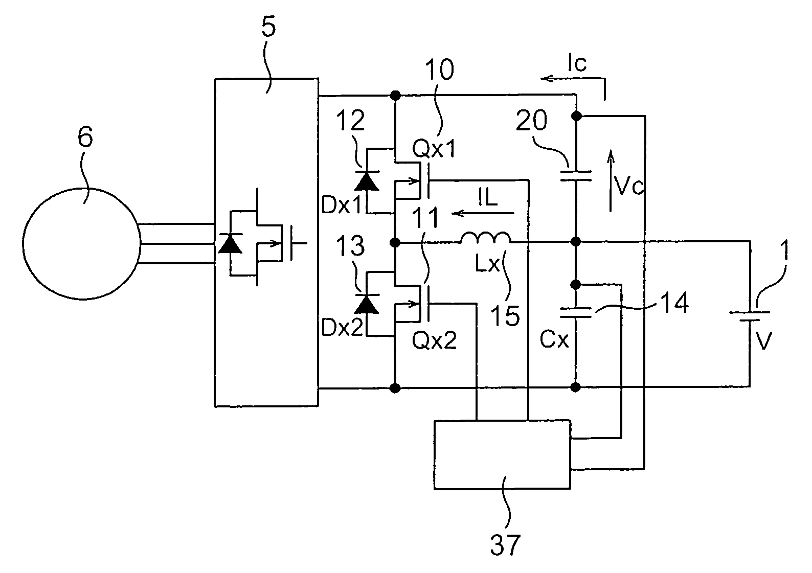
[0029]FIG. 1 shows a configuration of Embodiment 1 of the present invention. In FIG. 1, reference numeral 6 designates a motor which transmits a dynamic force to an engine (not shown) and starts it, and in turn receives a dynamic force of the engine during rotation thereof and generates an electric power. Reference numeral 1 is a battery which supplies a power for causing the motor 6 to rotate. Reference numeral 5 is a power conversion circuit which converts a voltage of the battery 1 into an alternating current or an interrupted direct current and outputs it to the motor 6. Reference numerals 10 and 11 are switching elements Qx1 and Qx2 (reference numerals 12 and 13), respectively. Reference numerals 12 and 13 are Diodes Dx1 and Dx2 connected in parallel to the switching elements 10 and 11 respectively. The switching elements 10 and 11 (Qx1, Qx2) are MOSFETs in which the diodes 12 and 13 (Dx1, Dx2) are disposed outside in parallel with parasitic diodes. The switching elements conne...

embodiment 2

[0050]FIG. 13 shows a circuitry of Embodiment 2 of the present invention. Embodiment 2 is different from Embodiment 1 (FIG. 1) in that a switching element 16 (Qx3) is disposed between the high-voltage-side terminal of the capacitor 20 and a drain terminal of the switching element (Qx1) constituted by a MOSFET. The switching element 16 (Qx3) is a MOFET.

[0051] An operation will be described. FIG. 14 shows running states of the vehicle and operating waveforms of the DC / DC converter in those states. Indicated as the operating waveforms are gate voltages of the switching elements 10, 11, and 16 (Qx1, Qx2, Qx3) (turned on at a high voltage), a current IL (whose positive direction is indicated by an arrow in FIG. 13) of the choke coil, a current Ic (whose positive direction is indicated by an arrow in FIG. 13) of the capacitor 20, and a voltage Vc (whose positive direction is indicated by an arrow in FIG. 13) of the capacitor 20.

[0052] As shown in FIG. 14, in a starting time period (T2) ...

embodiment 3

[0059]FIG. 6 shows a configuration of Embodiment 3 of the present invention. The configuration of Embodiment 3 is different from that of Embodiment 1 shown in FIG. 1 in that the capacitor 20 is dispensed with. Accordingly, the battery 1 is the only energy source, thus it is difficult to obtain a high-output power. However, as described above (FIGS. 5 and 8), it is possible to obtain a large power at a high voltage. If a condition of an idling stop operation of the vehicle can be satisfied on conditions shown in FIG. 8, a reduction in size and cost of the power unit are made possible to an extent corresponding to elimination of the capacitor 20.

[0060] An operation will be described. FIG. 15 similarly shows running states of the vehicle and operating waveforms of the DC / DC converter in those states. Indicated as the operating waveforms are gate voltages of the switching elements 10 and 11 (Qx1, Qx2) (turned on at a high voltage), a current IL (whose positive direction is indicated by...


PUM


Abstract

This invention provides a power unit for an automobile including a motor 6 for starting an engine by transmitting a power thereto and generating a power by receiving a power from the engine during rotation thereof, a power converting circuit 5 for transmitting a power to the motor 6, a battery 1, an energy storing source 20 for storing energy, and a DC/DC converter including at least two switching elements 10, 11, charging the energy storing source 20, and recovering energy in the energy storing source 20 to the battery 1. Since the switch provided in the DC/DC converter is normally turned on when the motor 6 generates power by receiving a power from the engine and charges the battery 1 through the power converting circuit 5 and the DC/DC converter, generation of heat from the DC/DC converter circuit part can be suppressed greatly.

Description

TECHNICAL FIELD [0001] The present invention relates to an automobile power unit, and more particularly to an automobile power unit that is mounted in a vehicle such as an automobile so as to be used as a battery. BACKGROUND ART [0002] In some of conventional automobile battery power circuits, a battery group and a capacitor group are connected in series, for example, as disclosed in JP 2002-218667 A (FIGS. 3 and 10). [0003] In the aforementioned JP 2002-218667 A, the battery group is composed of a single battery with a rated voltage of 12 V, and the capacitor group is composed of a plurality of capacitors. A DC / DC converter is connected between both ends of the capacitor group and the battery group, and supplies the battery group with a power by lowering a voltage of the capacitor group. Here, the battery group is intended to supply a power to an electrical component with a rated voltage of 12 V, and loads are connected to both ends of the battery group. [0004] In a conventional un...

Claims


Application Information

Patent Timeline
Patent Type & Authority Applications(United States)
IPC IPC(8): B60L8/00H02J7/34
CPCF02N11/04F02N11/0866H02J7/345F02N2011/0888F02N11/10Y02T10/7072
Inventor URAKABE, TAKAHIROOKUDA, TATSUYATSUNODA, YOSHIKAZU
Owner MITSUBISHI ELECTRIC CORP
Why Eureka
Try Eureka